Power Xpert ® Gateway Series 1000 Card User’s Guide
Class A EMC Statements FCC Part 15 NOTE This equipment has been tested and found to comply with the limits for a Class A digital device, pursuant to part 15 of the FCC Rules. These limits are designed to provide reasonable protection against harmful interference when the equipment is operated in a commercial environment.
Table of Contents 1 2 3 4 Getting Started . . . . . . . . . . . . . . . . . . . . . . . . . . . . . . . . . . . . . . . . . . . . . . . . . . . . . . . 1 Installation Checklist . . . . . . . . . . . . . . . . . . . . . . . . . . . . . . . . . . . . . . . . . . . . . . . . . . . . . . . . . . . . . . . . . . . Installing the Card . . . . . . . . . . . . . . . . . . . . . . . . . . . . . . . . . . . . . . . . . . . . . . . . . . . . . . . . . . . . . . . . . . . . . Connecting the Card . . . . . . . .
TABLE OF CONTENTS 5 Modbus Registers . . . . . . . . . . . . . . . . . . . . . . . . . . . . . . . . . . . . . . . . . . . . . . . . . . . . 49 Modbus Register Addressing . . . . . . . . . . . . . . . . . . . . . . . . . . . . . . . . . . . . . . . . . . . . . . . . . . . . . . . . . . . . . Modbus Function Codes . . . . . . . . . . . . . . . . . . . . . . . . . . . . . . . . . . . . . . . . . . . . . . . . . . . . . . . . . . . . . . Data Formats . . . . . . . . . . . . . . . . . . . . . . . . . . . .
Chapter 1 Getting Started NOTE If you have completed all sections in the Power Xpert Gateway Series 1000 Card Quick Start Instructions, proceed to Chapter 2, “Configuring the Card,” on page 19. This section explains: S Checklist items needed for installation S Installing the card S Connecting the card S Verifying or assigning the IP address S Configuring the network settings Installation Checklist 1.
GETTING STARTED 2. Provide your local network administrator with the card’s MAC address: - MAC Address Port 1 _________________________ - MAC Address Port 2 _________________________ The MAC address for Port 1 is located on a label on top of the card. To determine the MAC address of Port 2, increase the Port 1 address by one. For example: 0060261089A8 (Port 1), 0060261089A9 (Port 2). 3.
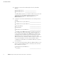
GETTING STARTED Installing the Card The hot-swappable PXGX Series 1000 Card can be installed without turning off the Powerware® Power Distribution Unit (PDU) or disconnecting the load. To install the PXGX Series 1000 Card: 1. Verify that all six DIP switches on the card are in the off position (see Figure 1). OFF ON Figure 1. Verify DIP Switches are OFF 2. Remove the X-Slot® cover from the PDU. Retain the screws.
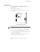
GETTING STARTED Figure 2. Install the PXGX Series 1000 Card 6. Connect an active Ethernet cable (supplied) to the Port 1 Ethernet connector on the PXGX Series 1000 Card (see Figure 3). If you are connecting a second network connection (separate subnet), connect an active Ethernet cable (not supplied) to the Port 2 Ethernet connector on the PXGX Series 1000 Card. Figure 3. Secure the Card and Install the Ethernet Cable 7.
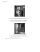
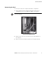
GETTING STARTED Connecting the Card To connect the card to the computer and start the configuration: 1. Plug the RJ-45 end of the supplied configuration cable into the configuration port on the card labeled “10101” (see Figure 4). NOTE Verify that you have used the port labeled “10101.” The other ports on the card do not work for configuration. Figure 4. Install Configuration Cable 2. Plug the other end of the serial cable into the serial COM port on the computer. 3.
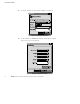
GETTING STARTED 4. Select the serial connection (such as COM1). See Figure 5. Figure 5. Select Serial Connection 5. Set the serial line to 9600 baud, No parity, 8 data bits, 1 stop bit, and no flow control (see Figure 6). Figure 6.
GETTING STARTED 6. Verify that the PDU is turned on. 7. After a few seconds, press Enter. The Network Settings menu appears in approximately one minute (see Figure 7). ------------------------------------------------------------------------ Network Settings -----------------------------------------------------------------------1. Ethernet Port 1 Settings 2. Ethernet Port 2 Settings 3. DNS Server (Primary) : [None] 4. DNS Server (Secondary) : [None] 5. Reset to Factory Defaults and Exit 0.
GETTING STARTED IP Address Assignments Many IT managers prefer the convenience of DHCP for managing the IP addresses of networked devices. With DHCP, the IT managers can easily reassign IP addresses as the network structure changes. In some cases, DHCP may not be available, or fixed IP addresses may be preferred for the PXGX Series 1000 Card (for example, if some other networked device needs to reach the card at a fixed address).
GETTING STARTED Verifying IP Addresses (DHCP Enabled) To verify the IP address assignments: 1. Type 1 and press Enter on the Network Settings menu (see Figure 7 on page 7) to display the Network Settings: Ethernet Port 1 menu (see Figure 8). -------------------------------------------------------------- Network Settings: Ethernet Port 1 -------------------------------------------------------------1. Dynamic Addressing (DHCP) Enabled 2. IP Address 10.222.51.250 3. Subnet Mask 255.255.255.0 4.
GETTING STARTED 9. Verify network communication by using a Web browser (see Figure 9). Type the IP address of the card and select Go. 10. The login prompt appears. The user name and default password is user for read-only information and admin for configuration (read/write) options. The PXGX Series 1000 Card Web page opens (see Figure 9). Enter the Card’s IP Address Figure 9. PXGX Series 1000 Card Web Page 11.
GETTING STARTED Assigning IP Addresses (DHCP Disabled) NOTE You can also set network settings via the PXGX Series 1000 Card’s Web page Network link (see “Network Configuration” on page 16). To manually enter fixed IP addresses for the card after you have connected it: 1. Type 1 and press Enter on the Network Settings menu (see Figure 10) to display the Network Settings: Ethernet Port 1 menu (see Figure 11).
GETTING STARTED -------------------------------------------------------------- Network Settings: Ethernet Port 1 -------------------------------------------------------------1. Dynamic Addressing (DHCP) Disabled 2. IP Address [None] 3. Subnet Mask [None] 4. Default Gateway [None] MAC Address Link Status 00:60:26:10:89:A8 Enabled 0. Exit to previous menu Select an option ==> 1 Enable DHCP? (y/n): n Figure 12. DHCP Control Option 3. Type n and press Enter to disable DHCP control. 4.
GETTING STARTED 9. Type 2 and press Enter on the Network Settings menu (see Figure 10 on page 11) to display the Network Settings: Ethernet Port 2 menu (see Figure 14). --------------------------------------------------------------- Network Settings: Ethernet Port 2 --------------------------------------------------------------1. Dynamic Addressing (DHCP) Enabled 2. IP Address [None] 3. Subnet Mask [None] 4. Default Gateway [None] MAC Address Link Status 00:60:26:10:89:A8 Enabled 0.
GETTING STARTED 12. Type 6 and press Enter to save and apply all settings (see Figure 16). 13. Type y and press Enter to confirm that you want to save and apply all settings and exit the utility. ------------------------------------------------------------------------ Network Settings -----------------------------------------------------------------------1. Ethernet Port 1 Settings 2. Ethernet Port 2 Settings 3. DNS Server (Primary) : 10.222.51.8 4. DNS Server (Secondary) : 10.222.1.75 5.
GETTING STARTED 14. Verify network communication by using a Web browser (see Figure 17). Type the IP address of the card and select Go. 15. The login prompt appears. The user name and default password is user for read-only information and admin for configuration (read/write) options. The PXGX Series 1000 Card Web page opens (see Figure 17). Enter the Card’s IP Address Figure 17. PXGX Series 1000 Card Web Page 16.
GETTING STARTED Network Configuration If you know the card’s IP address, you can configure the network settings from the card’s Web page: 1. Open a Web browser, type the IP address of the card, and select Go. 2. The login prompt appears. The user name and default password is user for read-only information and admin for configuration (read/write) options. Log in as admin. The PXGX Series 1000 Card Web page opens (see Figure 18). Enter the Card’s IP Address Figure 18. PXGX Series 1000 Card Web Page 3.
GETTING STARTED 5. If you will be using host names for controlling access to the card, enter the Domain, as well as the DNS IP addresses in the Nameserver fields. 6. If you will be using Simple Network Management Protocol (SNMP), identify the physical location of the installed PDU/card (sysLocation string) in the System location field. This value also appears in the card’s Web page header bar.
GETTING STARTED 18 EATON Power Xpert® Gateway Series 1000 Card User’s Guide S 164201670 Rev 1
Chapter 2 Configuring the Card NOTE If DHCP is disabled and you will be using host names for servers, such as the mail server, Network Time Protocol (NTP) server, SNMP hosts, Modbus®/TCP hosts, or trap recipients, enter the IP address of your network DNS Server (see “Network Configuration” on page 16). NOTE You must be logged in as admin to configure the card. Once you have logged in as admin, it is important to completely exit the browser to set the security level back to the standard read-only level.
CONFIGURING THE CARD Changing the Passwords The user name and default password is user for read-only information and admin for configuration (read/write) options. To change the passwords: 1. From the card’s Web page, click the Access Control link from the menu bar. 2. To change the user password, enter the new password in the ’user’ password field. The characters appear as asterisks (*). To change the admin password, log in as admin and enter the new password in the ’admin’ password field.
CONFIGURING THE CARD Setting the Date and Time NOTE All selections are automatically converted to Coordinated Universal Time (UTC). To set the date and time: 1. From the card’s Web page, click the Date/Time link from the menu bar. The default is to synchronize the date and time from the PC clock. 2. To synchronize the card with Network Time Protocol servers, select Synchronize with NTP server(s) and type the IP addresses or host names. You can synchronize the card with up to three NTP servers.
CONFIGURING THE CARD 4. To customize how the date appears in the card’s data and event logs, select a Date format for logs option (mm/dd/yyyy, dd/mm/yyyy, yyyy-mm-dd, or dd mmm yyyy). The default is mm/dd/yyyy. 5. To select the time zone for the card, specify the Timezone for Logs, email, and connected device. 6. Click Apply and then OK to save the settings.
CONFIGURING THE CARD 4. Click Apply and then OK to save the settings. 5. Repeat Steps 3 and 4 for each additional trap recipient. To remove a trap recipient, click Delete Last. Click OK when prompted to remove the settings for the trap recipient entered last. Restricting SNMP Access To limit access to the card from trusted SNMP NMS hosts only: 1. From the card’s Web page, click the Access Control link from the menu bar. 2. Activate the check box for SNMP access restricted by IP/hostname. 3.
CONFIGURING THE CARD Management from an SNMP NMS To access the PXGX Series 1000 Card via SNMP: 1. Use these default Community strings: GET Community string: public SET Community string: private 2. From the card’s Web page, click the Documentation link from the menu bar (or visit www.eaton.com/powerxpert) for the following MIB files for the PXGX Series 1000 Card: MIB Name Filename Description Eaton PDU MIB EATON-PDU-MIB.
CONFIGURING THE CARD Configuring Modbus TCP/IP Options To limit access to the card from trusted Modbus TCP/IP addresses only: 1. From the card’s Web page, click the Access Control link from the menu bar. 2. Activate the check box for Modbus-TCP access restricted by IP/hostname. 3. Type the trusted host’s IP addresses or host names, separated by a semi-colon, in the Trusted IPs/hostnames field.
CONFIGURING THE CARD Configuring E-mail Notification You may use the PXGX Series 1000 Card to inform selected e-mail accounts of events and changes in status as they occur in the PDU or to provide a status message at a predetermined time. To configure e-mail notification: 1. From the card’s Web page, click the Email link from the menu bar. 2. Enter the IP address or host name of the SMTP Server IP/hostname (mail server) that will be used to send the e-mail messages. 3.
CONFIGURING THE CARD 5. The e-mail Recipients are numbered. Select a number for a recipient. You can select different options for each recipient (Steps 6 through 10). After you enter and save an e-mail address, the Recipients list updates to show the recipient number and the corresponding e-mail address. 6. The default (True) is to send an e-mail when an event is activated and when it clears. Select False in the appropriate Send on event... fields to change these notification settings. 7.
CONFIGURING THE CARD Configuring EMP Settings NOTE Verify that the Power Xpert Gateway Card DIP switch #2 is set to the ON position, enabling the card for communication with an EMP. To configure the EMP settings: 28 1. From the card’s Web page, click the Environmental Monitoring Probe link from the menu bar. 2. For Contact #1 and #2, enter the Contact Description, such as External Contact #1 and External Contact #2. 3.
CONFIGURING THE CARD Configuring Auto Discovery Settings Configure the Auto Discovery settings so that the Power Xpert Software can find the PXGX Series 1000 Card on the network automatically. The card sends multicast discovery messages to any control Power Xpert host monitoring the specified Listen port. To configure the auto discovery settings: 1. From the card’s Web page, click the Auto Discovery link from the menu bar. 2. The default Listen port is 1900.
CONFIGURING THE CARD 30 EATON Power Xpert® Gateway Series 1000 Card User’s Guide S 164201670 Rev 1
Chapter 3 Root Certificate Authority Installation Improve the security of your PXGX Series 1000 Card on the Web by installing a root certificate authority (CA). A CA is a trusted third-party organization that issues digital certificates for use with encrypted digital transactions. The digital certificate guarantees that the company holding a certificate is who it claims to be.
ROOT CERTIFICATE AUTHORITY INSTALLATION Installing Root CA with Microsoft Internet Explorer 6 To install a certificate for the PXGX Series 1000 Card with Microsoft Internet Explorer 6: 1. Open the browser, type the IP address of the card in the address bar, and select Go. For example: https://10.222.51.236/ The Security Alert window opens (see Figure 19). Figure 19.
ROOT CERTIFICATE AUTHORITY INSTALLATION 2. Click the View Certificate button. The Certificate window opens (see Figure 20). Figure 20. Certificate Window NOTE The certificate cannot be verified yet because it is issued by a nontrusted CA.
ROOT CERTIFICATE AUTHORITY INSTALLATION 3. Select the Certification Path tab. The root CA is displayed as “Power Xpert Gateway Card” and the issued certificate is shown as the device’s IP address (see Figure 21). 4. Select Power Xpert Gateway Card. Figure 21.
ROOT CERTIFICATE AUTHORITY INSTALLATION 5. Click View Certificate. A new Certificate window opens for the CA (see Figure 22). Figure 22.
ROOT CERTIFICATE AUTHORITY INSTALLATION 6. Click Install Certificate.... The Certificate Import Wizard window opens (see Figure 23). Figure 23.
ROOT CERTIFICATE AUTHORITY INSTALLATION 7. Click Next. The Certificate Store window opens, prompting you to specify a certificate store (see Figure 24). Figure 24.
ROOT CERTIFICATE AUTHORITY INSTALLATION 8. Verify that the default setting, Automatically select the certificate store ..., is selected. 9. Click Next. The certificate wizard displays a final verification (see Figure 25). Figure 25. Verifying the Certificate Import Settings 10. Click Finish to complete the wizard. A message box similar to Figure 26 opens: Figure 26.
ROOT CERTIFICATE AUTHORITY INSTALLATION 11. Click Yes to install the CA. A new dialog box window opens to verify that the import was successful. 12. Close all windows except for the original Security Alert window (see Figure 19 on page 32). 13. Click View Certificate. An updated Certificate window opens showing a trusted certificate (see Figure 27). 14. Click OK. Figure 27. Updated Certificate Window 15. The installation process is complete.
ROOT CERTIFICATE AUTHORITY INSTALLATION Installing Root CA with Microsoft Internet Explorer 7 To install a certificate for the PXGX Series 1000 Card with Microsoft Internet Explorer 7: 1. Open the browser and type the IP address of the card followed by the path “/ca.html” in the address bar. For example: http://10.222.51.236/ca.html The following window displays (see Figure 28): Figure 28.
ROOT CERTIFICATE AUTHORITY INSTALLATION 2. Click Root CA Certificate. A File Download warning window opens (see Figure 29). Figure 29. File Download Warning 3. Click Open. The Certificate Window opens (see Figure 20 on page 33). 4. Follow the remaining steps for using Internet Explorer 6 (Step 3 on page 34 through Step 15 on page 39).
ROOT CERTIFICATE AUTHORITY INSTALLATION Installing Root CA with Mozilla Firefox To install a certificate for the PXGX Series 1000 Card with Mozilla Firefox: 1. Open the browser and type the IP address of the card followed by the path “/ca.html” in the address bar. For example: http://10.222.51.236/ca.html The following window displays (see Figure 30): Figure 30.
ROOT CERTIFICATE AUTHORITY INSTALLATION 2. Click Root CA Certificate. Firefox opens the Downloading Certificate window (see Figure 31). Figure 31. Downloading Certificate Window 3. If desired, click View to manually examine the contents of the certificate. 4. Click the Trust this CA to identify web sites check box option. 5. Click OK to complete the installation process. The installation process is complete. You can now access the card using the https protocol (for example, https://10.222.51.236).
ROOT CERTIFICATE AUTHORITY INSTALLATION 44 EATON Power Xpert® Gateway Series 1000 Card User’s Guide S 164201670 Rev 1
Chapter 4 MIB Files This chapter describes the Management Information Base (MIB) files available with the card. A MIB is an information repository residing on a device in a communication network. Network management software uses a device’s MIB to manage the device. Every manageable device on a network has a MIB consisting of one or more files that list information about the device.
MIB FILES Eaton PDU MIB The Eaton PDU MIB module contains objects and notifications for PDU, Panel, and Breaker information levels: S mainPDU S pduPanel S pduBreaker mainPDU Objects in this group describe the main PDU in the system. This group has three subgroups: S Nameplate Ratings subgroup. These objects provide the nominal rating values for the PDU. S Input Meters subgroup. These objects provide input meter values for the PDU.
MIB FILES Eaton EMP MIB Objects in this group are provided by the EMP and include temperature and humidity readings, alarming limits, the two contacts readings, and setup information. The group contains a table of values for environmental contact sensing (normally two digital inputs for monitoring all contacts). Traps are sent in response to EMP changes to indicate the type of alarm, alarm acknowledgement, and alarm clearing.
MIB FILES 48 EATON Power Xpert® Gateway Series 1000 Card User’s Guide S 164201670 Rev 1
Chapter 5 Modbus Registers This chapter describes how to address a specific Power Distribution Unit (PDU) or Remote Power Panel (RPP), a specific panel in a PDU or RPP, and a specific breaker in a panel using Modbus TCP/IP. NOTE To obtain the panel or circuit breaker data, the PDU/RPP must have the Energy Management System (EMS) Level 3 option installed. A PDU/RPP distributes power through one or more circuit breaker panels. Each panel consists of several circuit breakers.
MODBUS REGISTERS Modbus Register Addressing This section describes Modbus function codes, data formats, and data addressing. Modbus Function Codes The PDU/RPP registers are read using Modbus Function Codes (FC). For most PDU/RPP registers, FC 04 is used. The PDU/RPP supports the following hex function codes: Table 1.
MODBUS REGISTERS S TIME – The Time type (ymdhms) consists of six bytes specifying the year, month, day, hour, minutes, and seconds. The bytes are stored in hexadecimal format. If your Modbus application displays the individual bytes in a register, view the bytes using the decimal option. Otherwise, the bytes are best viewed by displaying the two-byte register in a binary format and translating each byte to decimal.
MODBUS REGISTERS PDU/RPP Unit ID Numbers Because the PDU/RPP consists of several panels of circuit breakers, set the Unit ID in the Modbus program to specify a specific PDU/RPP, a specific panel, or a specific breaker (see Table 2). The PDU/RPP has a Unit ID of 0, 1, or 255. The same PDU/RPP information can be obtained from any of these IDs. See “PDU/RPP Registers and Alarms” on page 54 for more information. The panel Unit IDs range from 2 to 17.
MODBUS REGISTERS Table 2.
MODBUS REGISTERS PDU/RPP Registers and Alarms This section contains information for the PDU/RPP Registers (FC 04) and PDU/RPP Alarms (FC 02). PDU/RPP Registers (FC 04) To read the vendor name in the PDU/RPP, set the Modbus program to Unit ID 1 and register 1001: IP: Unit ID: 1 Starting Register: 1001 Number of registers: 32 Function Code: 04 The PDU/RPP returns 32 registers containing up to 64 characters.
MODBUS REGISTERS Table 3.
MODBUS REGISTERS Table 3.
MODBUS REGISTERS Table 3.
MODBUS REGISTERS Table 4.
MODBUS REGISTERS Table 4.
MODBUS REGISTERS Table 4.
MODBUS REGISTERS For example, the AC Voltage between Phase A and Neutral is available in register 4010.
MODBUS REGISTERS Table 5.
MODBUS REGISTERS Table 5. Panel Summary Registers (FC 04) (continued) Name Register Data Type Bytes MIN Frequency 11022 FLOAT 4 MAX Frequency 11027 FLOAT 4 Panel Alarms (FC 01 or 02) Table 6 lists the panel alarms. They are not registers, but are discrete inputs and are read using FC 01 or FC 02.
MODBUS REGISTERS Breaker Data and Alarms This section contains: S Names of breaker parameters along with the register numbers for Breaker #1 S Instructions for calculating the register numbers for other breakers S Breaker alarms Breaker #1 Data Registers (FC 04) To specify a specific breaker, use a Unit ID for breaker data along with the register number for the specific breaker. For example, “Watts in Phase A” is register 1055 for Breaker #1. This statement is true for any panel.
MODBUS REGISTERS Table 7.
MODBUS REGISTERS Calculating Breaker Register Numbers Table 7 shows the register numbers for Breaker #1. There can be many breakers in a panel.
MODBUS REGISTERS Breaker Alarms (FC 01 or 02) There are two alarms for each circuit breaker: Overload Warning and Overload. Each alarm has a unique address similar to the data registers, but these alarms are not data registers. The alarms are discrete inputs and are read using FC 01 or FC 02 in the Modbus program. Table 8.
MODBUS REGISTERS Environmental Monitoring Probe (FC 03 or 04) The optional Environmental Monitoring Probe for the PDU/RPP can measure temperature and humidity. Because the device can be located outside the PDU/RPP, the reference is to “auxiliary” data. In addition, it contains two connections for monitoring the condition of auxiliary input contacts, such as a door switch. See Table 9 for a list of EMP registers. An exception code is returned if the EMP is not installed.
Chapter 6 Specifications Table 10.
SPECIFICATIONS 70 EATON Power Xpert® Gateway Series 1000 Card User’s Guide S 164201670 Rev 1
Chapter 7 Operation and Maintenance This section explains: S Indicator descriptions S DIP switch settings S Generating log files S Firmware upgrade instructions Front-Panel Indicator Descriptions The Ethernet port indicator descriptions for the PXGX Series 1000 Card are listed in Table 11; the stacked indicator descriptions are listed in Table 12. Table 11.
OPERATION AND MAINTENANCE Table 12. Stacked Indicator Descriptions Label Color Illuminated Not Illuminated STATUS Green Communication with the PDU has been established. Communication with the PDU has not been established. As the card boots, the indicator remains off. However, if it remains off after one minute, there is a communication problem between the card and the PDU. DHCP Amber At least one port is configured for DHCP and has obtained IP address information.
OPERATION AND MAINTENANCE DIP Switch Description DIP switch definitions for the PXGX Series 1000 Card are listed in Table 13. Table 13. DIP Switch Definitions S1 Position Number OFF Position (Default) ON Position 1 Enable previously stored network configuration settings (Normal mode) Override network settings to assign private IP addresses (Configuration mode); Port 1 is set to 192.168.1.1 and Port 2 is set to 192.168.1.
OPERATION AND MAINTENANCE Generating Log Files NOTE The data log and event log files are comma-separated values (*.csv) files that can be opened in Microsoft Excel software. Some computer configurations will automatically open the files in the Microsoft Excel software instead of prompting you to save. To generate a data log: 1. From the card’s Web page, click the Data Log link from the menu bar. 2. Click the Click to generate button. 3. Select a name and location for the file (if prompted to save).
Chapter 8 Service and Support If you have any questions or problems with the PXGX Series 1000 Card, call your Local Distributor or the Help Desk at one of the following telephone numbers and ask for a PXGX Series 1000 Card technical representative.
SERVICE AND SUPPORT Two-Year Limited Warranty (US and Canada) Power Xpert Gateway (PXGX) Series 1000 and Series 2000 Cards WARRANTOR: The warrantor for the limited warranties set forth herein is Eaton Electrical Inc., a Delaware Corporation company (“Company”).
SERVICE AND SUPPORT Company shall not be responsible for any charges for testing, checking, removal or installation of Warranted Items. COMPANY DOES NOT WARRANT EQUIPMENT NOT MANUFACTURED BY COMPANY. IF PERMITTED BY THE APPLICABLE MANUFACTURER, COMPANY SHALL PASS THROUGH SUCH MANUFACTURER’S WARRANTIES TO END-USER. COMPANY DOES NOT WARRANT SOFTWARE (IF APPLICABLE TO THE PRODUCT), INCLUDING SOFTWARE EMBEDDED IN PRODUCTS, THAT IS NOT CREATED BY COMPANY.
SERVICE AND SUPPORT 78 EATON Power Xpert® Gateway Series 1000 Card User’s Guide S 164201670 Rev 1
*1642016701* 164201670 1