Powerware® BladeUPS ® Bar Installation Guide
Special Symbols The following are examples of symbols used on the UPS or accessories to alert you to important information: RISK OF ELECTRIC SHOCK - Observe the warning associated with the risk of electric shock symbol. CAUTION: REFER TO OPERATOR’S MANUAL - Refer to your operator’s manual for additional information, such as important operating and maintenance instructions. This symbol indicates that you should not discard the UPS or the UPS batteries in the trash.
Table of Contents 1 Introduction . . . . . . . . . . . . . . . . . . . . . . . . . . . . . . . . . . . . . . . . . . . . . . . . . . . . . . . . . 1 Safety Warnings . . . . . . . . . . . . . . . . . . . . . . . . . . . . . . . . . . . . . . . . . . . . . . . . . . . . . . . . . . . . . . . . . . . . . . 2 Installation . . . . . . . . . . . . . . . . . . . . . . . . . . . . . . . . . . . . . . . . . . . . . . . . . . . . . . . . . . 5 Inspecting the Equipment . . . . . . . . . . . . . . . . . . . . .
TABLE OF CONTENTS ii EATON Powerware® BladeUPS® Bar Installation Guide S 164201723 Rev P01
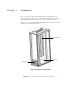
Chapter 1 Introduction Up to six of Eaton’s Powerware® BladeUPS® uninterruptible power systems (UPSs) can be installed in an industry standard rack outfitted with a BladeUPS Bar 60 for interconnecting the cabinets’ wiring. Figure 1 shows an installed BladeUPS Bar 60. The wireway fits into the bottom 6U of standard rack space. BladeUPS Bar 60 Wireway Front Covers Figure 1.
INTRODUCTION Safety Warnings IMPORTANT SAFETY INSTRUCTIONS SAVE THESE INSTRUCTIONS This manual contains important instructions that you should follow during installation and maintenance of the BladeUPS Bar 60. Please read all instructions before operating the equipment and save this manual for future reference. VIGTIGE SIKKERHEDSANVISNINGER GEM DISSE ANVISNINGER Denne manual indeholder vigtige instruktioner, som skal følges under installation og betjening af BladeUPS Bar 60-enheden.
INTRODUCTION WICHTIGE SICHERHEITSANWEISUNGEN AUFBEWAREN Dieses Handbuch enthält wichtige Hinweise, welche Sie bei der Installation und Wartung des BladeUPS Bar 60 beachten sollten. Bitte lesen Sie alle Anweisungen des Handbuches bevor sie mit dem Gerät arbeiten. Bewaren Sie das Handbuch zum Nachlesen auf. IMPORTANTI ISTRUZIONI DI SICUREZZA CONSERVARE QUESTE ISTRUZIONI Il presente manuale contiene importanti istruzioni da seguire durante l’installazione e il funzionamento di BladeUPS Bar 60.
INTRODUCTION INSTRUCCIONES DE SEGURIDAD IMPORTANTES GUARDE ESTAS INSTRUCCIONES Este manual contiene instrucciones importantes que debe seguir durante la instalación y el funcionamiento del BladeUPS Bar 60. Por favor, lea todas las instrucciones antes de poner en funcionamiento el equipo y guarde este manual para referencia en el futuro.
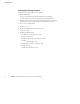
Chapter 2 Installation This section explains: S Equipment inspection S BladeUPS Bar 60 setup and installation Inspecting the Equipment If any equipment has been damaged during shipment, keep the shipping cartons and packing materials for the carrier or place of purchase and file a claim for shipping damage. If you discover damage after acceptance, file a claim for concealed damage.
INSTALLATION Checking the Package Contents Verify that the following items are included: S BladeUPS Bar 60 A six-socket bar with (1) attached terminal block assembly, (1) attached base bracket, and (3) attached mounting brackets S Wireway main housing with (2) attached side brackets, (1) attached terminal block housing, and (1) attached wireway access cover S Front cover mounting panel S (2) front covers S Ferrite assembly with 38 cm (15”) tie wrap S This user’s guide S Packaged hardware items: - (14) M
INSTALLATION Installation To install the BladeUPS Bar 60: 1. Remove the access cover and terminal block housing from the wireway housing (see Figure 2). Retain the wireway terminal block housing, wireway access cover, and screws. Leave the two side brackets installed on the wireway housing (see side bracket locations in Figure 3). 2. Verify that the side brackets are in the most closed position and that the adjustment screws are tightened to prevent the side brackets from moving.
INSTALLATION 4. Install an M6 hex nut onto each of the three wireway studs to secure the wireway to the rear of the rack. Install the first stud in the fourth hole location from the bottom. Do not tighten the nuts. Figure 4 shows the nuts installed. 5. Loosen the three adjustment screws on each side of the wireway housing and adjust the side brackets for the depth of the rack. Do not retighten the screws. 6.
INSTALLATION 9. Place the ferrite assembly on the floor of the wireway and secure with the supplied tie wrap. Loop the tie wrap through both attachment sites on the wireway floor and through the ferrite assembly. See Figure 4. 10. Note the orientation of the base bracket installed on the bar for later re-installation (see Figure 5). Remove and retain the base bracket and hardware. 11. Place the bar in the rack as shown in Figure 4. NOTE The bar can rest on the floor of the rack until secured in place.
INSTALLATION NOTE Verify that the bar is secure as shown in Figure 4. The sheetmetal at the base of the bar should be below the tab on the wireway floor. 12. Secure the bar to the wireway with three M6×12 hex bolts. Install the bolts from the front of the rack. See Figure 5. Torque the bolts to 5.1 ± 0.8 Nm (45 ± 7 lb in). 13. Reinstall the base bracket removed in Step 10. Install the bolts from the front of the rack. See Figure 5. Torque the bolts to 5.1 ± 0.8 Nm (45 ± 7 lb in).
INSTALLATION 14. Secure the base bracket to the rack with three M6×12 hex bolts. Install the bolts from the rear of the rack. Use a large screwdriver or crowbar to lift the bar in place to align the holes in the base bracket with the holes in the rack. Install the lowest bolt in position 2, then use positions 9 and 15. Verify that the base bracket stud aligns completely with the rack hole below the top bolt (position 14). See Figure 6. Torque the bolts to 5.1 ± 0.8 Nm (45 ± 7 lb in). 15.
INSTALLATION 16. Install two M4×8 pan-head screws into the tab on the wireway floor, securing the base of the bar to the wireway. See Figure 7. Torque the screws to 1.7 ± 0.2 Nm (15 ± 2 lb in). M4×8 Pan-Head Screws (2 places) Rear of Rack Wireway Floor Tab (above bar base sheetmetal) Figure 7.
INSTALLATION 17. Using two M6×12 hex bolts, secure the left side of the wireway terminal block housing to the rack. See Figure 8. Torque the bolts to 5.1 ± 0.8 Nm (45 ± 7 lb in). 18. Using nine M4×8 pan-head screws, secure the wireway terminal block housing to the wireway and to the bar. See Figure 8. Torque the screws to 1.7 ± 0.2 Nm (15 ± 2 lb in). Wireway Terminal Block Housing M6×12 Hex Bolts (2 places) M4×8 Pan-Head Screws (9 places) Figure 8.
INSTALLATION 19. Using five M4×8 pan-head screws, install the wireway access cover. See Figure 9. Torque the screws to 1.7 ± 0.2 Nm (15 ± 2 lb in). M4×8 Pan-Head Screws (5 places) Wireway Access Cover Figure 9. Wireway Access Cover Installation 20. Verify the six information labels are attached to the wireway as shown in Figure 10. Figure 10.
INSTALLATION 21. Using four M5×16 hex bolts and four M5 cage nuts, secure the front cover mounting panel to the front of the rack. Verify that the bent edge of the panel is at the top. See Figure 11. Install the lower bolts and cage nuts into the second holes from the bottom of the rack frame. Torque the bolts to 5.1 ± 0.8 Nm (45 ± 7 lb in). Bent Edge of Panel M5×16 Hex Bolts and M5 Cage Nuts (4 places) Front Cover Mounting Panel Front of Rack Figure 11.
INSTALLATION 22. Snap the two front covers into place, as shown in Figure 12. Front Covers (2 pieces) Figure 12.
Chapter 3 Specifications This section provides the following specifications: Table 1. BladeUPS Bar 60 Dimensions (WxDxH) Depth of Wireway Weight 14.0×11.3×183.8 cm (5.5”×4.4”×72.4”) 90.1 cm (35.
SPECIFICATIONS 18 EATON Powerware® BladeUPS® Bar Installation Guide S 164201723 Rev P01
Chapter 4 Service and Support If you have any questions or problems with the BladeUPS Bar, call your Local Distributor or the Help Desk at one of the following telephone numbers and ask for a UPS technical representative.
SERVICE AND SUPPORT 20 EATON Powerware® BladeUPS® Bar Installation Guide S 164201723 Rev P01
*164201723P01* 164201723 P01