Vickers® Piston Pumps Overhaul Manual PVE Variable Pump 12–21 USgpm capacity at 1800 rpm Released 8/1/90 M-2854-S
Table of Contents Section Page I. Introduction . . . . . . . . . . . . . . . . . . . . . . . . . . . . . . . . . . . . . . . . . . . . . . . . . . . . . . . . . . . . . . . . . . . . . . . . . . . . . . . . . . . . 3 A. Purpose of Manual . . . . . . . . . . . . . . . . . . . . . . . . . . . . . . . . . . . . . . . . . . . . . . . . . . . . . . . . . . . . . . . . . . . . . . . . . . . . 3 B. General Information (Related Publications/Model Code) . . . . . . . . . . . . . . . . . . . . . . . . . . . . . . .
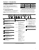
Section I – Introduction A. Purpose Of Manual Model Series This manual describes operational characteristics and overhaul information for the PVE12, 19(*) and the PVE21(*)–** variable displacement piston pumps. The information contained herein pertains to the latest design series as listed in Table 1.
1 1 Pump, Variable Displacement, Inline Piston, E–Series 2 Flow Rating USgpm @ 1800 rpm 19 – 19 USgpm 21 – 21 USgpm 3 Shaft Rotation (Viewed from shaft end) R – Right hand (clockwise) L – Left hand (counterclockwise) 4 Input Shaft Type 1 – SAE B Straight keyed 2 – SAE B 15 tooth splined 9 – SAE B 13 tooth spline 5 2 6 3 4 5 6 7 Control Options (** = Pressure setting in tens of bars) C-10 – Pressure compensated (PVE19, 250-3000 psi) (PVE21, 250-2700 psi) CG-10 – Remote control pressure compe
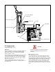
Housing Compensator Yoke Shaft Seal Shaft Bearing Piston Valve Block PVE12 Section View Wafer Plate Yoke Compensator Tapered Roller Bearing Drive Shaft Housing Rotating Group PVE19 Section View Figure 1.
Section II – Description A. General Assembly of a typical pump package is shown in Figure 1. Six types of compensator subassemblies are used with the PVE series pumps. Refer to Section III for principles of operation. See Model Code for pressure settings. 1. Compensator (C), (Flat Cut-Off Type): A pump using this compensator will maintain a constant load pressure for all values of flow within the capacity of the pump. 2.
Section III – Principles of Operation A. Piston Pump Rotation of the pump drive shaft causes the cylinder block, shoe plate and pistons to rotate. See Figure 2. The piston shoes are held against the yoke face by the shoe plate. The angle of the yoke face imparts a reciprocating motion to each piston within the cylinder block. Inlet and outlet ports connect to a kidney slotted wafer plate.
Cross Hole (Open to Spring Area) Compensator Spring Pump Load Drain Yoke Spring Yoke Stroking Piston Compensator Spool Outlet Inlet Rotating Group Figure 3. Flat Cut-Off Compensator D. Compensator CAUTION (Load Sensing Type - “CV”) Application A frequent application of pressure compensator pumps is to supply sevo valves or mechanically operated metering valves, whose function is to control flow to a hydraulic actuator (cylinder or motor).
Actuator Load External Valve Spool Orifice (nP-Pressure Drop) Compensator Spring Drain Yoke Stroking Piston Yoke Spring Compensator Spool Outlet Relief Valve Rotating Group Inlet Figure 4. Load Sensing Compensator (CV). Circuit Operation At Minimum Pressure External Valve Spool Orifice Size Reduced Refer to Figure 4 during the following description. Assume a no load condition.
External Valve Spool Orifice Size Increased If the external valve spool orifice size is increased, pump outlet pressure will decrease, lowering force against the compensator spool. (See Figure 4.) The compensator spring causes the spool to move, opening the yoke stroking piston to case drain. As fluid is metered from the yoke stroking piston, the yoke spring force strokes the yoke to a higher flow.
Set Screw Compensator Spring Compensator Spool Actuator Load External Valve Spool Orifice Drain Yoke Stroking Piston Yoke Spring Load Sensing Spool Outlet Inlet Rotating Group Figure 5.
Section IV – Installation and Operating Instructions A. Installation Drawings D. Piping and Tubing The installation drawing listed in Table 2 will show installation dimensions and port locations. 1. All pipes and tubing must be thoroughly cleaned before installation. Recommended methods of cleaning are sand blasting, wire brushing, and pickling. B. Mounting and Drive Connections NOTE For instructions on pickling, refer to instructions sheet 1221-S.
Sound Level H. Start-Up Noise is only indirectly affected by the fluid selection, but the condition of the fluid is of paramount importance in obtaining optimum reduction of system sound levels. Before starting pump the case MUST be filled with clean hydraulic fluid.
Section V – Service and Maintenance A. Service Tools The following standard tools for overhauling the piston pump are shown in Figure 8. Standard Tools and Equipment: 1. Torque wrench with short extension and sockets 4. Air bubbles in the reservoir can ruin the pump and other components. If bubbles are seen, locate the source of the air and seal the leak. (See Table 3). 5. A pump which is running excessively hot or noisy is a potential failure.
1 1.500 1.232 .005 Use for Intermediate shaft bearing installation Drive shaft bearing installation Drive shaft bearing removal 1 1/2” heavy wall tubing 2 3 5 “A” .005 6 4 “A” 4” 6” 9” Figure 9. Special Shaft Bearing Removal and Installation Tools. Figure 8. Standard Tools. 0.1875 thread 1/2” -13 thru 1/4” bolt hole loose fit. “A” “B” 1/4” 1/2” 0.120 “C” 2” Bearing Race Puller Description A Valve Block 1.675 Housing 2.125 B 1.300 1.625 C 1.250 1.
“C” Nominal Pipe Size “B” A B C 1 1/2” 4” 1.625 1.900 2” 4” 2.125 2.375 Schedule 80 (extra heavy) .375 “A” .005 Figure 11. Special Bearing Race Installation Tools. 6.50 1.500 .375 1.439 1.440 Heavy wall tubing 0.250 2.500 .005 0.125 Press ring on end of tubing. Aluminum ring Figure 12. Shaft Seal Driver. F. Replacement Parts Reliable operation throughout the specified operating range is assured only if genuine manufacturer’s parts are used.
G. Troubleshooting Table 3 lists the common difficulties experienced with piston pumps and hydraulic systems. It also indicates probable causes and remedies for each of the troubles listed. TROUBLE PROBABLE CAUSE REMEDY Excessive pump noise. Low oil level in the reservoir Fill reservoir to proper level with the recommended transmission fluid. DO NOT over fill transmission or damage may result. Air in the system Open reservoir cap and operate hydraulic system until purged.
Section VI – Overhaul c. Remove lockwire (4), plug (5) and O-Ring (7) (6 and 7 on the CV compensator). A. General CAUTION Before breaking a circuit connection, make certain that power is off and system pressure has been released. Lower all vertical cylinders, discharge accumulators, and block any load whose movement could generate pressure. After removing the pump from the system and before disassembly, cap or plug all ports and disconnected hydraulic lines.
67 68 74 69 66 65 32 28 23 71 64 36 70 38 25 39 41 31 29 26 43 35 37 34 40 42 44 72 59 57 58 60 33 30 49 50 51 52 53 54 55 35 36 34 27 27 Refer to Service Drawings for assembly instructions and torque values.
PVE 19/21 Figure & Index No.
10 9 1 24 8 7 6 5 4 3 2 72 60 49 50 51 59 58 57 56 30 52 53 54 55 25 62 61 46 44 45 27 55 54 53 52 51 50 47 48 49 Figure 13.
1 23 24 10 3 2 9 8 7 5 11 21 19 18 20 4 12 17 16 15 13 14 67 71 70 68 69 73 63 26 29 64 34 43 42 41 40 38 37 36 35 33 28 32 31 65 66 39 22
3. Inspect spring (8) and (16) for wear and parallelism. Spring ends must be parallel. Replace if spring is warped or wear is evident. 4. Inspect seat (9) for wear in the area of spool contact. 5. Inspect spool (10) for excessive wear, galling, scratches, etc. If scratches exist across the spool land, replace the spool and inspect the body bore. Rotate the spool while moving in and out of the bore to check the binding. Binding cannot be tolerated.
Figure 14. Cylinder block subassembly disassembly tool. (Tighten nut, remove snap ring, loosen nut to relieve spring tension). F. Inspection Repair and Replacement 1. Check bearing (32) for scoring or brinelling of the rollers (PVE 19/21). 2. Check bearing spacer (33) for burrs (PVE 19/21). 3. Inspect cylinder block S/A face (34) for wear, scratches and/or erosion between cylinders. Check the spring, washers and retaining ring located within the cylinder block S/A. 4.
NOTE If shims (51) were destroyed during disassembly, a yoke bearing preload adjustment must be made at assembly. c. Slide the yoke from side to side to loosen the yoke bearing races (54) within the housing. The races are a normal slip fit but may be tight. Use an open end wrench between the yoke and the pintle bearing to help slide out the races. Apply pressure to bearing (55) at the approximate center and allow the bearing rollers to gently press the race out of the housing. 15.
Arbor Press Here Shoulder Figure 16. Removal of Front Bearing Race. Retaining Ring 1 1/2” heavy wall tubing 6” long. See Figure 11. Arbor Press Here Shaft Seal Figure 18. Front Bearing Installation. G. Assembly of Housing Parts NOTE If a new shaft bearing (61), shaft (48), valve block (26), or housing (27) is required, a complete preload adjustment must be performed. If the same parts are returned to service, the preload adjustment can be omitted.
a. Assemble pintle bearings (55) on each end of the yoke and insert bearing races (54). b. Install bearing spacer (53) at one pintle end. c. Install O-Ring (52) against spacer (53) into the groove, then install a 0.010 inch shim (51) under pintle cover (50). Install four pintle cover screws (49) and torque to 175–185 lbf. in. NOTE Early designs used a screw and washer arrangement. These should be torqued to 115–125 lbf. in. d. Set housing (27) on its side so the other pintle is up.
H. Disassembly of Valve Block 1. Do not disassemble check valve parts (64) through (66), unless action of the valve indicates a problem. Check the valve action with a pencil or a screwdriver. Press the check valve in against the spring, it should return and hold firm against the seat. If the check valve is defective, remove and replace the complete assembly. Press new seat (64) flush with face of valve block. DO NOT scratch the face of valve block (26). 2.
2. Install pipe plug (69) into valve block (26) and secure. 3. Assemble a new O—Ring (68) on hex plug (67) and thread plug into place. 2. Assemble wafer plate (28) over the bearing race (pins on the PVE12) and locating pin (29) with wear surface away from valve block (26). Determine from the model code which wafer plate is used. See Figure 22. K.
Section VII – Test Procedure A. Test Conditions FLUID MEDIUM: SAE 10W meeting API service classification MS or equivalent. FLUID TEMPERATURE: 120°F ±5°F at pump outlet. Fluid entering the pump must be maintained below a maximum contamination limit of class four according to NAS1638. B. Preliminary Check 1. Rotate the drive shaft through one complete revolution. The shaft must rotate with less than 8 N.m (6 lbf. ft.) torque and be free without evidence of binding. 2.
2. Refer to Figure 23 and adjust load valve (1) and globe valve (1) to 100 PSI system pressure at P1. Observe maximum pump flow and maximum case leakage requirement noted in Table 4. F. Performance Test of PVE 12/19/21 Piston Pump with “CG” Compensator Control 1. Operate pump at 1200 RPM. Set remote control valve to minimum pressure setting. P1 P3 Q1 Piston Pump Bypass Check #1 P2 Cooler Q2 M V1 Filter V2 Figure 23. Circuit Diagram for “C” and “CG” Control.
G. Performance Test of PVE 12/19/21 Piston Pump with “CV”, “CVP”, “CVPC” and “CVPD” Compensator Control NOTE Refer to Figure 24 for location of circuit components. 1. Open load valve one (1) and turn compensator adjustment plug clockwise until seated. 2. Operate at 1200 RPM and 100 Psig outlet pressure until all air is removed from the test circuit. 3. The case leakage as read at flow rater Q2 must exceed 10cc/minute. Make sure globe valve V2 is open. 4. Adjust globe valve V1 closed.
Compensator Pressure Setting Psig Lockwire Standby Pressure P2 PVE12*-*-**-C**VP11 3000 Yes 250 psi Max. PVE12*-*-**-C**VPC24 3000 Yes PVE12*-*-**-C**VPD41 3000 Yes Model PVE19*-*-**-CV-10 PVE21*-*-**-CV-10 PVE19*-*-**-CVP-12 PVE21*-*-**-CVP-12 PVE19*-*-**-CVPC-12 PVE21*-*-**-CVPC-12 500 psi Max. 900 psi Max. P@ USgpm (P2-P1) 160 psi ± 20 psi 4 USgpm 350 psi ± 25 psi 4 USgpm 600 psi ± 50 psi 4 USgpm 160 psi ± 20 psi 6.5 USgpm 160 +20 –30 psi 350 psi ± 25 psi 6.