
Installation Sheet

OPERATION
Depress the test switch. The LED heads will light and the
charge LED will extinguish. LED heads will illuminate as
long as the button is pushed. Release the test switch. The
charge LED will illuminate and the LED heads will turn off.
MAINTENANCE:
None required. Replace the batteries as needed according
to ambient conditions. Equipment should be tested every
30 days in accordance with local codes.
NOTE: Servicing of any parts should be performed by quali-
fi ed personnel. Only use replacement parts supplied by Ea-
ton Light. Use of unauthorized parts may void the warranty.
CAUTION: This equipment is furnished with a sophisticated
low voltage battery dropout circuit to protect the battery
from over discharge after its useful output has been used.
Allow 24 hours recharge time after installation or power
failure prior to 90 minute testing.
TROUBLE SHOOTING GUIDE
If LED heads or charge indicator LED does not illuminate,
check the following:
1. Check AC supply – verify that unit has 24 hour AC
supply.
2. Unit is shorted or battery is not connected.
3. Battery discharged. Permit unit to charge for 24 hours
and then re-test.
4. If following the above trouble shooting hints does not
solve your problem, contact your local Eaton Light rep-
resentative for assistance
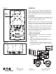
Figure 2
Figure 1
FOR BEST
RESULTS MOUNT
WITH ARROW
FACING UP
Eaton
1121 Highway 74 South
Peachtree City, GA 30269
eaton.com/lighting
© 2015 Eaton
All Rights Reserved
Printed in USA
Eaton is a registered trademark.
All trademarks are property of
their respective owners.
JMP12
JMP11
JMP10
JMP9
JMP8
JMP7
JMP6
JMP5
JMP4
BATT
LAMPS
N
c
TDI
ICSP
277
JMP13
JMP14
LED/SW
D5
C6
C7
C8
C9
CN4
F1
J1
JK1
LED1
MOV1
MOV2
PR1
Q1
Q5
R7
R10
R13
R15
R18
R30
SW1
120
CN5
+
+
WHITE LEAD - TO NEUTRAL
BLACK LEAD - TO 120V
ORANGE LEAD - TO 277V
CHARGER/DRIVER PCB
BATTERY
LED HEADS