Eka Gas Meter Node User’s Guide Document Number XXXX Revision 01 Eka Systems, Inc. 20201 Century Boulevard, Suite 250 Germantown, MD 20874 USA www.ekasystems.
EKA CONFIDENTIAL Confidential and Proprietary Reproduction or Distribution Prohibited This document is for informational purposes only. It contains information that is confidential and proprietary. This document has been prepared by and is the property of Eka Systems, Inc. By accepting and reviewing this document, you agree that you will treat its contents as confidential and proprietary, and that you will not copy, distribute or otherwise disclose the information contained herein to third parties.
Contents 1 About the Eka Gas Meter Node............................................................................................................. 4 2 Eka Gas Meter Node Hardware ............................................................................................................. 5 2.1 Node Layout ...................................................................................................................................... 7 2.2 Installation and Configuration ...............................
1 About the Eka Gas Meter Node The Eka Gas Meter Node is designed for installation in Datamatic FIREFLY Meter Interface Units. The node obtains data from the Meter Interface Unit, and uses an integrated radio transceiver to communicate data to an associated network. The node communicates with a nearby EkaNet network, enabling the meter to be read remotely. [photo of node] The node is powered by a battery attached to the FIREFLY Meter Interface Unit. The battery is field-replaceable.
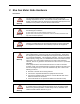
2 Eka Gas Meter Node Hardware FCC Notice Warning The Original Equipment Manufacturer (OEM) must ensure that FCC Labeling requirements are met. This includes a clearly visible label on the outside of the OEM enclosure specifying the appropriate EKA Systems FCC identifier for this product as well as the FCC Notice below. This device complies with Part 15 of the FCC Rules.
Warning To comply with FCC RF exposure compliance requirements, the antenna used for this transmitter must be installed to provide a separation distance of at least 20 cm from all persons and must not be co-located or operate in conjunction with any other antenna or transmitter.” As such, the radio component of this device is intended only for OEM integrators under the following two conditions: The antenna must be installed such that 20 cm is maintained between the antenna and users.
2.1 Node Layout The Eka Gas Meter Node is shown in the photograph below. [photo with callouts for key features that user’s need to know about] Each Gas Meter Node is identified by a unique serial number. This number is displayed on the label and is encoded in the bar code. Additionally, the serial number is embedded in the node’s firmware. The serial number is displayed on the Field Tool and in the Network Manager to identify the node. 2.
2.3 Operation Node data is retrieved by the EkaNet Network Manager software at intervals set by the utility company. Data consists of pressure compensated total gas consumption as of the last time the meter was read by the Gas Meter Node. Note: RF communications during data reporting are the single largest drain on the node’s battery. For maximum battery life, it is recommended that the data reporting interval be set at the maximum (once each 24 hours).
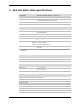
3 Eka Gas Meter Node Specifications Application Specifications Compatibility Datamation FIREFLY Meter Integration Unit Data storage Stores 45 days of data (1 channel @ 1 hour intervals) Data integrity Non-volatile data storage provides extra security in the event of communication failure or power outage Advanced features Load profile, remote demand reset Radio Specifications Operating frequency 902 – 928 MHz Reliable data transmission Error detection, correction and retransmission RF output powe
Operating Conditions Environmental XXXXX-01 -40° C to +85° C 0 – 95% non-condensing humidity Power supply Battery pack installed in FIREFLY Meter Integration Unit Power consumption 0.
20201 Century Boulevard, Suite 250 Germantown, MD 20874 USA www.ekasystems.