
User's Manual


XXXXX-01 7 Eka Gas Meter Node User’s Guide
2.1 Node Layout
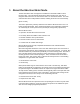
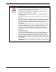
The Eka Gas Meter Node is shown in the photograph below.
[photo with callouts for key features that user’s need to know about]
Each Gas Meter Node is identified by a unique serial number. This number is displayed
on the label and is encoded in the bar code. Additionally, the serial number is embedded
in the node’s firmware. The serial number is displayed on the Field Tool and in the
Network Manager to identify the node.
2.2 Installation and Configuration
The Eka Gas Meter Node is designed specifically for installation in Datamatic FIREFLY
Meter Integration Units. Installation instructions for the node and its companion battery
are provided in the “Eka Gas Meter Node Installation Manual.”
The Eka Gas Meter Node is configured over a local RF link using the Eka Field Tool.
Programmable parameters include:
z Meter serial number.
z Node serial number.
z Node description.
z Meter’s latitude and longitude.
z Local standard time in relation to UTC (Coordinated Universal Time).
z Meter’s reading when the node was installed.
z Read interval (5 minutes, 15 minutes, 30 minutes, 1 hour or up to 24 hours in 1 hour
increments; factory default is 1 hour).
z Reporting interval (factory default is daily).
z Report cycle start date (factory default is 1st of the month).
z Gas volume per dial rotation (default value is 1).
z Meter measurement units (CF, CCF, MCF and Cubic Meters; default is cubic feet, CF).
z Pressure compensation ratio (normally printed on the meter index face plate; default is
1.0).
z High flow alarm threshold in units/minute, where units is the meter measurement units
(see above).
Note: All changes made to remotely programmable parameters become effective by 8:00am
the day after the changes are made.