
Cut Sheet

Volume 8—Sensing Solutions CA08100010E—July 2015 www.eaton.com V8-T5-23
5
5
5
5
5
5
5
5
5
5
5
5
5
5
5
5
5
5
5
5
5
5
5
5
5
5
5
5
5
5
5.1
Photoelectric Sensors
Enhanced 50 Series Sensors
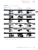
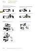
Wiring Diagrams
Pin numbers are for reference, rely on pin location when wiring.
Enhanced 50 Series Sensors
Notes
1
Connecting the test input to 0 Vdc allows you to switch the light source off for troubleshooting while leaving the sensor under power.
2
Over current protection is to be provided in the field. Conductor size for 20 AWG: 5 amp; 22 AWG: 3 amp; 24 AWG: 2 amp.
3
Connect load to appropriate output for either sinking or sourcing operation.
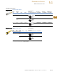
Operating
Voltage Cable Model
Mini-Connector Model
(Face View Male Shown)
Micro-Connector Model
(Face View Male Shown)
Thru-Beam Source
10–40 Vdc
All Others
10–40 Vdc
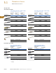
Thru-Beam Source
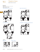
12–240 Vdc or 24–240 Vac
solid-state relay
2
All Others with Isolated AC/DC Output
12–240 Vdc or 24–240 Vac
solid-state relay
2
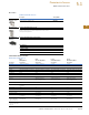
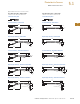
Thru-Beam Source
12–240 Vdc or 24–240 Vac
SPDT EM relay
2
All Others
12–240 Vdc or 24–240 Vac
SPDT EM relay
2
BU
BR
BK
Test In
(+)
(
–
) OV
1
Test In
(
–
)
OV
(+)
Test In
(
–
)
OV
(+)
BU
WH
NPN
PNP
(
–
)
OV
BK
BN
(+)
Load
Load
(+)
(
–
)
OV
PNP
NPN
Load
Load
(+)
(
–
)
OV
PNP
NPN
Load
Load
BU
BR
L1
(+)
L2
(
–
)
L2
(
–
)
L1
(+)
L1
(+)
L2
(
–)
BU
BK
WH
BR
L1
(+)
L2
(
–
)
Isolated
AC/DC Output
3
L2
(
–
)
L1
(+)
Isolated
AC/DC Output
3
L1
(+)
L2
(
–
)
Isolated
AC/DC
Output
3
BU
BR
L1
(+)
L2
(
–
)
L2
(
–
)
L1
(+)
L1
(+)
L2
(
–)
BU
OR
BK
BR
WH
N.C.
COM
N.O.
L2
(
–
)
L1
(+)
L1
(+)
COM
N.O. N.C.
L2
(
–
)
L1
(+)
L2
(
–
)
COM
N.O. N.C.