
Cut Sheet
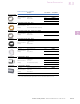

V8-T8-14 Volume 8—Sensing Solutions CA08100010E—November 2013 www.eaton.com
8
8
8
8
8
8
8
8
8
8
8
8
8
8
8
8
8
8
8
8
8
8
8
8
8
8
8
8
8
8
8.4
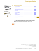
Sensor Accessories
Pilot Devices
Technical Data and Specifications
Pilot Devices
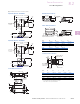
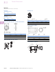
Wiring Diagrams
Pin numbers are for reference, rely on pin location when wiring.
Output Circuits and Connections Relay Contact Output
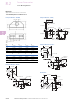
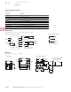
Dimensions
Approximate Dimensions in Inches (mm)
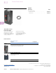
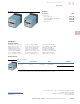
Control Unit Socket with Terminals
Description
Specification
Input voltage 110 to 120V/220 to 240 Vac ± 10%, 50/60 Hz
Temperature range 14° to 122°F (–10° to 50°C)
Relative humidity Less than 85%
Response time Less than 20 ms
Output voltage 12 Vdc ± 10%, 100 mA maximum
Short-circuit and polarity protection Incorporated
Power consumption Less than 8 VA
Terminal connections Screw and saddle clamp to accept 14 AWG wire
Output SPDT relay contact rated 3A resistive at 250 Vac
Black
Red
White
Black
Red
Green
External Sync. Input
CONTROL UNIT
Emitter
Thru-Beam
Reciever
or Reective
Type Sensor
*Power
Input
Contact
Output
1
2
3
4
5
6
7
8
9
10
11
12
+12
IN
+12
0
COM
NO
NC
*Power Input
1 and 2: 110 to 120 Vac
1 and 3: 220 to 240 Vac
(5)
NO
NC
COM
(6)
(4)
Contact Capacity
3A Resistive at 250 Vac
0.02
(0.5)
2.56 (65)
2.44 (62)
2.36
(60)
4.45 (113)
4.29 (109)
4.07 (103.5)
0.96
(24.5)
1.97 0.04
(50 1)
Mounting Hole
1.97
(50)
Qty. 2 — 0.18 (4.5) Dia. Drilled
or Qty. 2 – M4 Tapped
0.22
(5.5)
0.18
(4.5)
2.36
(60)
0.35
(9)
0.30 (7.7)
2.44 (62)
0.75
(19)
0.96
(24.5)