
Cut Sheet


V8-T12-18 Volume 8—Sensing Solutions CA08100010E—November 2012 www.eaton.com
12
12
12
12
12
12
12
12
12
12
12
12
12
12
12
12
12
12
12
12
12
12
12
12
12
12
12
12
12
12
12.1
Sensor Learning Course
Learning Module 23: Limit Switches, Proximity Sensors and Photoelectric Sensors
Inductive Proximity Sensor Influences
When applying inductive
proximity sensors, it is
important to understand the
sensing range and the factors
that influence that range. The
sensing range refers to the
distance between the
sensor face and the target.
It also includes the shape of
the sensing field generated
through the coil/core.
There are four main concerns
when selecting and applying
proximity sensors:
●
Target considerations
(material, size, shape and
approach)
●
Coil size and shielding
●
Sensor mounting
requirements
●
Environment
Target Material
You need to know the
target’s material. This
information will help you
determine the maximum
sensing distance. Exceed this
distance, and the damping
effect necessary to trip the
sensor’s output will not be
created—and the sensor will
fail to sense the target.
Proximity sensors work
best with ferrous metals.
Though these sensors detect
other metals, the range will
not be as great. Generally,
the less iron in the target, the
closer the target has to be to
the sensor to be detected.
Manufacturers generally
provide charts showing the
necessary correction factors
for various types of metals
when applying their sensors.
Each sensor style will have a
correction factor to enable
calculation for a particular
target material.
Target Size
The size of the target also
matters. If you run a target
smaller than the sensor’s
“standard size,” sensing
range will decrease. This is
because a smaller target
creates a weaker eddy
current. However, a bigger
target does not mean a
longer sensing range.
The thickness of the target
does not impact sensing
range much. However, a very
thin non-ferrous target can
actually achieve a greater
sensing range because it
generates an eddy current on
both sides (known as the foil
effect).
So, how big should the target
be? The rule of thumb is:
the size of the sensor’s
diameter, or three times the
sensor’s sensing range,
whichever is greater.
Target Shape
The shape of the target can
have an impact on the
sensing range. A round
object, or an object with a
rough surface can affect the
damping effect of the sensor,
and may require a closer
sensing distance. Using a
larger sensor size or an
extended range sensor will
also minimize this effect.
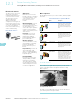
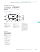
Target Approach
How the target approaches
the sensor matters as well.
When an object comes at the
sensor straight on, that’s an
axial approach. With this
type of approach, you will
need to protect the sensor
physically. Allow for 25%
overtravel.
Axial Approach
Hysteresis tends to be
greater for an axial approach
than a lateral approach.
Lateral Approach
On a slide-by, or lateral
approach, the target
approaches the center axis
of the sensing field from
the side.
The target should not pass
closer than the basic
tolerance built into the
machine design. Targets
bumping into your sensor are
a sure guarantee of eventual
poor sensor performance.
For both approach types,
make sure the target
passes not more than 75%
of the sensing distance
from the sensor face. It is in
this “tip” area that variations
in the sensing range occur.
2 Sn
Sn
Core
D
0.75
x
D
Recommended
Sensing Area
Target
Sensing
Distance of
Target Used
(Will Be Sn
for Standard
Target)