
Cut Sheet


V8-T12-30 Volume 8—Sensing Solutions CA08100010E—November 2012 www.eaton.com
12
12
12
12
12
12
12
12
12
12
12
12
12
12
12
12
12
12
12
12
12
12
12
12
12
12
12
12
12
12
12.1
Sensor Learning Course
Learning Module 23: Limit Switches, Proximity Sensors and Photoelectric Sensors
Excess Gain
Definition
Excess gain is a
measurement of how much
sensing power a
photoelectric sensor has
available beyond the power
required to detect an
object.
An excess gain of 1.00 at a
given range means there is
exactly enough power to
detect an object under
perfect conditions at that
range. In other words, the
range at which the excess
gain equals 1.00 is the
maximum range of the
sensor.
Every model of sensor comes
with an excess gain chart to
help you determine the
excess gain for an
application’s sensing
distance.
However, we have to take
into consideration the
following real-world variables:
●
Target size
●
Target color
●
Target surface texture
●
Ability to block the beam
●
Background
●
Application environment
In the real world, there is
contamination—dust,
humidity and debris—that can
settle on the lenses and
reduce light transmission.
Furthermore, each individual
target may vary slightly from
the next in color, reflectivity
or distance from the sensor.
If you use a sensor with an
excess gain of exactly 1.00,
you stand an excellent
chance of not sensing the
target reliably. To cover
yourself, you need a sensor
with the highest excess
gain possible at the
intended range. This
ensures the sensor will
continue to operate reliably
when you need it. As the
level of contamination gets
worse, more excess gain will
be needed to get past the
poor visibility.
Thru-Beam
This type of sensor’s excess
gain is the simplest to
measure. Excess gain is
almost exclusively a
function of the separation
between the source unit
and the detector unit.
When implementing the
excess gain for an
application, start with the
excess gain chart for the thru-
beam sensor. Then consider:
●
Misalignment of the two
units
●
Dirt in the environment
reduces gain
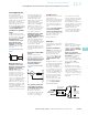
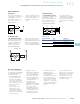
Typical Gain Curve for a
Thru-Beam
How to read the gain
graph. If these sensors are
spaced 30 ft apart, the
excess gain at that distance
would be an excess gain
of “10”.
Diffuse Reflection
Nearly every diffuse
reflective sensor has a
unique combination of
lenses and beam angles.
As a result, nearly every
sensor has a unique excess
gain curve.
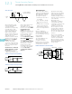
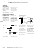
Diffuse Reflection Ranges
Long Range Perfect Prox
Example
Short Range
Focused Diffused Reflective
8. 13102A Typical
9. 13102A Minimum
Sensing range of diffuse
mode sensors referenced to
90% reflective white target.
A short-range sensor
delivers high excess gain
over a short sensing
distance and drops off
quickly. The source’s beam
and the detector’s field of
view converge a short
distance from the lenses.
The energy present in that
area is very high, allowing
the detection of small
targets. The sensor also
ignores objects in the near
background.
Short-Range and
Long-Range
A long-range sensor’s source
beam and detector’s field of
view are positioned close
together on the same axis.
The ability to sense extends
quite a distance. Excess gain
peaks out several inches
from the sensor, then drops
off slowly over distance.
To sense into holes or
cavities, or to pick up very
small objects, use a
focused diffuse reflective
sensor. Or, a sensor with a
very small light spot size. The
source and detector are
positioned behind the lens in
order to focus the energy to a
point. The excess gain is
extremely high at this point
and then drops off on either
side of the sensing zone.
1000
10
1
10.1 10 10 0
100
Range (ft)
X
Long Range (in)
4000
1000
100
10
1
0.1 10 20 30 40 50 60 70 100
1000
Short Range (in)
100
10
1
0.1 10 1001
1000
10
1
10.1 10 10 0
RANGE (inches)
100
RANGE (mm)
252.5 254 2540
8
9
EXCESS GAIN
Long Range Proximity
Short Range Proximity