
User manual
2 Engineering
2.10 Switching to the output side
DC1 Variable Frequency Drive 04/16 MN04020003Z-EN www.eaton.com 49
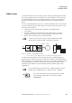
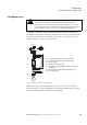
2.10 Switching to the output side
Typical applications for switching at the DC1 variable frequency drive’s
output include:
• Cases in which a bypass circuit is implemented.
• Cases in which it must be possible to switch on various motors as
necessary.
• Cases in which several motors are connected in parallel and need to be
switched individually.
• Cases in which the motor must be de-energized quickly in the event of
an emergency stop (safety shutdown).
When an individual motor is switched off, the inverter needs to be disabled
first (the FWD/REV enable signal must be switched off) before the contacts
(contactor, switch-disconnector) are opened.
In cases in which the output is switched to a running motor, parameter
P-33 must have a value of 1 (flying restart circuit enabled). When this
condition is met, the DC1 variable frequency drive will be automatically
synchronized with the running motor with the enable signal (FWD/REV).
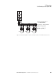
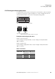
2.10.1 Contactors
The contactors on the output side of DC1 variable frequency drives need to
be sized based on utilization category AC-3 (IEC/EN 60947-4-1) for the
assigned rated motor current and the corresponding rated operating voltage
(as with DOL starting).
→
Variable frequency drives with a frame size of FS1 do not
feature the “flying restart circuit” function. In this case, when
parameter P-33 has a value of 1, DC braking will be activated
and the running motor will be slowed down using DC injection.
In this case, the contacts on the DC1 variable frequency drive’s
output side need to be closed before the variable frequency
drive is enabled (FWD/REV) in order to activate DC braking.
The P-32 (t-DCBraking@Stop) and P-11 (U-Boost) parameters
can be used to adjust the DC braking duration and intensity.
→
Vacuum contactors are not suitable for switching at low
frequencies and should not be used at the output of DC1
variable frequency drives.