
User manual

3 Installation
3.3 Mounting
60 DC1 Variable Frequency Drive 04/16 MN04020003Z-EN www.eaton.com
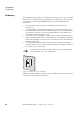
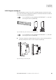
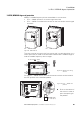
When variable frequency drives with internal fans are installed vertically over
each other, an air baffle must be placed between the devices. Failure to do
so may expose the device on top to a thermal overload caused by the guided
air flow (device fan).
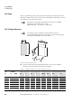
Figure 25: Deflector due to increased circulation caused by device fan
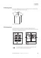
Table 3: Recommended values for minimum clearances and required cooling air
(see fig. 24, 25)
→
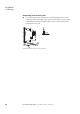
Devices with high magnetic fields (e. g. reactors or
transformers) should not be installed close to the variable
frequency drive.
Size a b c Airflow
1)
mm in mm in mm in m
3
/h ft
3
/min
For degree of protection IP20
FS1
50 1.97 33 1.3 50 1.97 18.69 11
FS2 50 1.97 46 1.81 75 2.95 37.38 22
FS3
2)
50 1.97 52 2.05 100 3.94 101.94 60
FS4 50 1.97 52 2.05 100 3.94 203.88 120
For degree of protection IP66
FS1 10 0.39 12.5 0.49 200 7.87 – –
FS2 10 0.39 12.0 0.47 200 7.87 – –
FS3
2)
10 0.39 13.0 0.51 200 7.87 – –
1) ft
3
/min = CFM (cubic foot per minute)
2) For UL conformity, the maximum permissible ambient air temperature over a period of 24 hours is limited to
+45 °C for the DC1-127D0…, DC1-32011…, and DC1-32018… variable frequency drives.
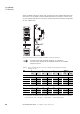
cc
V
V
VAR
EMC