
User manual
3 Installation
3.5 EMC installat ion
66 DC1 Variable Frequency Drive 04/16 MN04020003Z-EN www.eaton.com
3.5 EMC installation
The responsibility to comply with the legally stipulated limit values and thus
the provision of electromagnetic compatibility is the responsibility of the end
user or system operator. This operator must also take measures to minimize
or remove emission in the environment concerned. He must also utilize
means to increase the interference immunity of the devices of the system.
The technology and system of a variable frequency drive cause the flow of
high frequency leakage current during operation. Because of this, all earthing
elements must be low-impedance elements connected in such a way as to
establish an electrical contact across a large surface area.
With leakage currents greater than 3.5 mA, in accordance with VDE 0160 or
EN 60335, either
• the cable cross-section of the protective conductor must be 10 mm
2
,
• the protective conductor must be open-circuit monitored, or
• the second protective conductor must be fitted.
For an EMC-compliant installation, we recommend the following measures:
• installation of the variable frequency drive in a metallically conductive
housing with a good connection to ground,
• screened motor cables (short cables).
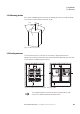
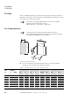
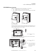
3.5.1 EMC measures in the control panel
In order to have an installation that meets EMC requirements, make sure to
connect all the metallic parts in the devices and in the control panel to each
other across a large area and in a way that will make it possible to conduct
high frequencies. Mounting plates and control panel doors should be
connected to the panel by means of short drain wires with an electrical
contact established across a large surface area.
→
In a magnet system (PDS) with variable frequency drives, you
should take measures for electromagnetic compatibility (EMC)
while doing your engineering, since changes or improvements
to the installation site, which are required in the installation or
while mounting, are normally associated with additional higher
costs as well.
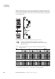
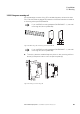
→
Ground
all conductive components and housings
in
a drive
system
using
as short a line as possible with the greatest
possible cross-section (Cu-braid).
→
Do not make connections to painted surfaces (electrolytic
oxidation, yellow chromated).
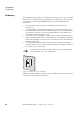
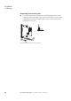
→
Install the variable frequency drive as directly as possible
(without spacers) on a metal plate (mounting plate).