
User manual


3 Installation
3.5 EMC installat ion
DC1 Variable Frequency Drive 04/16 MN04020003Z-EN www.eaton.com 67
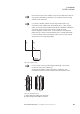
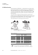
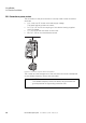
Figure 34: Cable routing
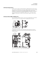
Figure 35: Separate routing
a Power cable: mains voltage, motor connection
b Control and signal lines, fieldbus connections
→
Route mains and motor cables in the control cabinet as close to
the ground potential as possible. This is because free moving
cables act as antennas.
→
If routed in parallel, cables carrying high frequencies (e.g.,
screened motor cables) and clean cables (e.g., mains supply
cable, control and signal cables) should be installed at a distance
of at least 100 mm from each other in order to avoid
electromagnetic interference. You should also use separate
cable entries if there is a great difference in voltage potentials.
If control cables and power cables need to cross, they should
always do so at a right angle (90°).
→
Do not route the control and signal cables in the same
conduit as the power cables .
Analog signal cables (measured values, setpoints, and
correction values) must be routed inside screened conduit.
≧ 100 mm
(≧ 3.34“)
②①
a
b
a
b