
User manual


3 Installation
3.5 EMC installat ion
74 DC1 Variable Frequency Drive 04/16 MN04020003Z-EN www.eaton.com
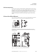
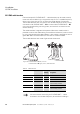
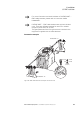
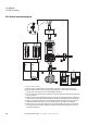
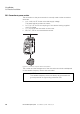
3.5.6 General installation diagram
Figure 40: EMC installation
a Mains connection: Supply voltage, central earthing connection for control panel and machine
b External radio interference suppression filter: Optional DX-EMC… radio interference suppression
filter for longer motor cables or use in a different EMC environment
c Control connection: Connection for the digital and analog control cables and communication via RJ45
plug-in connection
d Motor connection: Connection (PES) between the screened motor cable and the motor’s terminal box,
made according to EMC requirements, with metal cable gland or with gland plate in the terminal box.
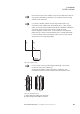
e Cable routing: Power cables (A) and control cables (B) spatially routed separately from each other.
If different potential levels need to cross, they should do so at a right angle as far as possible.
f Cable routing: Do not route power cables and control cables parallel to each other in a single cable
duct. If they need to be routed in parallel, they should be in separate metal cable ducts (in order to
meet EMC requirements).
L2/N L3DC- L1/L
DC+ BR U V W
12345678910111213
14 15 16 17 18
COM
~ AC
PES
PES
PE
≧ 100 mm
(≧ 3.34“)
PES
UVW
PE
PES
UVW
PE
BA
⑤
⑥
AB AB
④
①
②
③