
User manual

3 Installation
3.6 Electrical Installation
DC1 Variable Frequency Drive 04/16 MN04020003Z-EN www.eaton.com 87
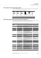
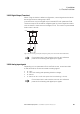
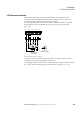
3.6.2.1 Terminal capacities and stripping lengths
The terminal capacities and stripping lengths are listed in the following table.
Table 10: Control signal terminal sizes and designs
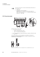
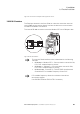
3.6.2.2 Control signal terminal connection information and functions
The functions that are set in the ex-factory and the electrical connection data
of all control signal terminals are listed in the following table.
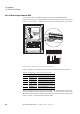
Table 11: Factory-set functions of the control signal terminal
M3
mm
2
mm
2
AWG mm in N/m ft-lbs mm
0.2 - 2.5 0.2 - 1.5 24 - 12 5 0.2 0.5 0.42 0.4 x 2.5
Connection
terminal
Signal Description Default settings
1+24V Control voltage for DI1
- DI4, output (+24 V)
Maximum load 100 mA,
Reference potential 0 V
–
2DI1
Digital input 1 +8 - +30 V (High, R
i
>6kΩ) Start enable FWD
3DI2 Digital input 2 +8 - +30 V (High, R
i
>6kΩ) Start enable REV
4DI3
AI2
Digital input 3
Analog input 2
• digital: +8 - +30 V (high)
• Analog: 0 - +10 V (R
i
> 72 kΩ)
0/4 - 20 mA (R
B
=500Ω)
Can be switched with parameter P-
16
•1 - 10kΩ
Fixed frequency FF1
5+10V
Reference voltage,
Output (+10 V)
Maximum load: 10 mA
Reference potential: 0 V
–
6AI1
DI4
Analog input 1
Digital input 4
• Analog: 0 - +10 V (R
i
>72kΩ)
0/4 - 20 mA (R
B
=500Ω)
Can be switched with parameter P-
16
•1 - 10kΩ
• digital: +8 - +30 V (high)
Frequency reference
value
(fixed frequency)
70V
Reference potential 0 V = connection terminal 9 –
8AO1
DO1
Analog output 1
Digital output 1
• Analog: 0 - +10 V, maximum 20 mA
Can be switched with parameter P-
25
• digital: 0 - +24 V
Output Frequency
90V
Reference potential 0 V = connection terminal 7 –
10 K13 Relay 1, N/O Maximum switching load:
250 V AC/6 A or 30 V DC/5 A
RUN
11 K14
Relay 1, N/O Maximum switching load:
250 V AC/6 A or 30 V DC/5 A
RUN