
User manual

3 Installation
3.6 Electrical Installation
92 DC1 Variable Frequency Drive 04/16 MN04020003Z-EN www.eaton.com
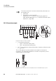
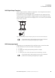
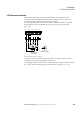
3.6.2.7 Analog output signal
There is an analog voltage signal (0 - 10 V) available at control signal
terminal 8. This output can handle a maximum load of 20 mA.
Parameter P-25 is used to configure whether this output signal will be
provided at the terminal.
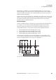
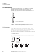
3.6.2.8 Relay contact
Control signal terminals 10 and 11 are connected to the DC1 variable
frequency drive’s internal relay contact (N/O) in a potential-free manner.
The relay function can be configured with parameter P-18.
The electrical connection specifications for control terminals 10 and 11 are:
• 250 V AC, max. 6 A
• 30 V DC, max. 5 A
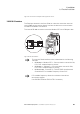
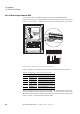
We recommend connecting the loads connected to the relay contact as
follows:
Figure 56: Analog output (AO)
(connecting example)
→
Control terminals 7 and 9 are the common 0 V reference
potential for all analog and digital input signals.
9
0...+10 V
AO
8
OV
< 20 mA
f-Out
-
+
250 V ∼ : ≦ 6A
30 V ⎓ : ≦ 5A
10
RUN
11
K13
K14
K1
I
AC
DC
AC
Varistor
(+)
(
-
)
DC
Diode
AC
RC filter