Manual 11/16 MN04020004Z-EN PowerXL™ DC1 Variable Frequency Drives Parameter Manual Parameter Designation Value Description DS P00-01 Analog Input1 0 - 1000 Analog input 1 Level of the signal applied to analog input 1 after scaling and offsets have been applied. 0 P00-02 Analog Input 2 0 - 1000 Analog input 2 Level of the signal applied to analog input 2 after scaling and offsets have been applied. 0 P00-03 Frequency Reference -P-01 - +P-01 Frequency Reference in Hz.
All proprietary names and product designations are brand names or trademarks registered to the relevant title holders. Break-Down Service Please call your local representative: http://eaton.com/moeller/aftersales or Hotline After Sales Service: +49 (0) 180 5 223822 (de, en) AfterSalesEGBonn@eaton.
Danger! Dangerous electrical voltage! Before commencing the installation • Disconnect the power supply of the device. • Ensure that devices cannot be accidentally restarted. • Verify isolation from the supply. • Earth and short circuit the device. • Cover or enclose any adjacent live components. • Follow the engineering instructions (AWA/IL) for the device concerned. • Only suitably qualified personnel in accordance with EN 50110-1/-2 (VDE 0105 Part 100) may work on this device/system.
II
Table of contents 0 About this manual ..................................................................... 3 0.1 Target group................................................................................. 3 0.2 List of revisions ............................................................................ 3 0.3 0.3.1 0.3.2 0.3.3 Writing conventions ..................................................................... Hazard warnings of material damages .........................................
2 4 Messages .................................................................................... 29 4.1 List of messages.......................................................................... 29 4.2 Messages after a data transfer with a DX-COM-STICK ............... 31 5 Parameter ................................................................................... 32 5.1 “Monitor” parameter group......................................................... 32 5.2 “Basic” parameter group...........
0 About this manual 0.1 Target group 0 About this manual This manual provides special information that is intended to enable you to configure the parameters for a DC1 variable frequency drive according to your needs. The details apply to the indicated hardware and software versions. → For a general description (installation, technical data, etc.) of DC1 variable frequency drives, please refer to manual MN04020003Z (“Installation Manual”). 0.
0 About this manual 0.3 Writing conventions 0.3 Writing conventions Symbols with the following meaning are used in this manual: ▶ Indicates instructions to be followed. 0.3.1 Hazard warnings of material damages NOTICE Warns about the possibility of material damage. 0.3.2 Hazard warnings of personal injury CAUTION WARNING DANGER → Indicates useful tips. → All the specifications in this manual refer to the hardware and software versions documented in it.
1 General 1.1 Parameter Groups 1 General 1.1 Parameter Groups The DC1 variable frequency drive's functions are configured with the use of parameters. These parameters are subdivided into three groups (P0-00, P-01 to P-14, and P15 to P-55): Table 1: Parameter Groups Parameter group Theme P0-00 Monitor P-01 – P-14 Basic P-15 – P-55 Extended → The following page („Menu structure“) features a diagram showing how to switch between parameter groups.
1 General 1.2 Menu structure Extended P01 02 P15 16 ∙ ∙ ∙ ▲▼ ▲▼ ▲▼ ∙ ∙ ∙ ∙ ∙ ∙ ∙ ∙ ∙ Monitor Basic 1.2 Menu structure OK P0001 02 P000 19 20 13 14 54 55 Level 1 Password entry Level 2 (password set with: P-37; default password = 101) 6 DC1 Variable Frequency Drives 11/16 MN04020004Z-EN www.eaton.
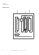
2 Control unit 2.1 Control unit elements 2 Control unit 2.1 Control unit elements The following figure shows the elements of the DC1 variable frequency drive integrated operating unit.
2 Control unit 2.2 Setting parameters 2.2 Setting parameters Table 3: Navigating within the keypad Description Commands Press the OK button and hold it down for two seconds in order to access the parameter interface → The display will show the parameter that was last used. Use the ▲ and ▼ buttons to select a parameter Press the OK button. Use the ▲ and ▼ buttons to change the parameter's value Press the OK button to confirm the parameter value change.
2 Control unit 2.4 Extended parameter set 2.4 Extended parameter set Table 5: Enabling and disabling access to the extended parameter set Commands Description Enabling access to the extended parameter set Press the OK button and hold it down for two seconds in order to access the parameter interface → The display will show the parameter that was last used. Use the ▲ and ▼ buttons to select parameter P-14 Press the OK button.
2 Control unit 2.5 “Monitor” submenu 2.5 “Monitor” submenu Table 6: “Monitor” submenu Description Commands Accessing the "Monitor" submenu Access to parameter level 2 must have already been enabled with P-14. Use the ▲ and ▼ buttons to select parameter P-00. Press the OK button. → The submenu with P00-01 to P00-20 will now be accessible. Navigating within the "Monitor" submenu Use the ▲ and ▼ buttons to select parameters P00-01 to P00-20. Press the OK button to confirm.
2 Control unit 2.6 Control via keypad 2.6 Control via keypad Table 7: Control via keypad Button Attribute ID Explanation OK P-12 = 1 or = 2 • P-12 = 1: one operating direction (FWD) • P-12 = 2: two operating directions (FWD/REV) START Starts the variable frequency drive ▲ Increase speed ▼ Decrease speed START Changes the operating direction if the motor is running Note: Only if P-12 = 2 OK Changes the value being displayed: A, rpm, etc.
3 Control signal terminals 3.1 Correspondence between inputs/outputs and terminals 3 Control signal terminals 3.1 Correspondence between inputs/outputs and terminals Input/Output Clips Entries DigIN: 1 Terminal 2 DI2 Terminal 3 DI3/AI2 Terminal 4 DI4/AI1 Terminal 6 Outputs AO1/DO1 Terminal 8 RO1 (relay, N/O) Terminals 10/11 Parameter P-15 can be used to select the configuration for the control signal terminals.
3 Control signal terminals 3.1 Correspondence between inputs/outputs and terminals The following abbreviations are used throughout this document: Table 8: Abbreviations Abbreviation Significance AI1 REF Analog input AI1 (terminal 6) Used as a speed setpoint input. • P-16: configuration (voltage input, current input etc.) • P-35: scaling • P-39: offset AI2 REF Analog input AI2 (terminal 4) Used as a speed setpoint input. • P-47: configuration (voltage input, current input etc.
3 Control signal terminals 3.1 Correspondence between inputs/outputs and terminals Abbreviation Significance Select AI1 REF/AI2 REF Used to select between the analog setpoint values on AI1 (terminal 6) and AI2 (terminal 4) • AI1 = Low • AI2 = High Select AI1 REF/f-Fix Used to select between the analog speed reference value at analog input 1 (AI1 = terminal 6) and a fixed frequency. The fixed frequency itself can be selected with the Select f-Fix Bit0, Select f-Fix Bit1, Select f-Fix Bit2 commands.
3 Control signal terminals 3.1 Correspondence between inputs/outputs and terminals Abbreviation Significance Select PI REF/f-Fix1 Used to select between setpoint values • Low = setpoint from the PI controller's output • High = f-Fix1, set with P-20 Select t-dec/t-Quick-dec This command must be present (there must be a high-level signal at the corresponding terminal) in order to be able to run the variable frequency drive.
3 Control signal terminals 3.2 Configuration of the control signal terminals 3.2 Configuration of the control signal terminals 3.2.
3 Control signal terminals 3.2 Configuration of the control signal terminals 3.2.
3 Control signal terminals 3.2 Configuration of the control signal terminals 3.2.
3 Control signal terminals 3.2 Configuration of the control signal terminals 3.2.
3 Control signal terminals 3.2 Configuration of the control signal terminals 3.2.
3 Control signal terminals 3.2 Configuration of the control signal terminals 3.2.
3 Control signal terminals 3.2 Configuration of the control signal terminals 3.2.
3 Control signal terminals 3.2 Configuration of the control signal terminals 3.2.
3 Control signal terminals 3.2 Configuration of the control signal terminals 3.2.
3 Control signal terminals 3.2 Configuration of the control signal terminals 3.2.
3 Control signal terminals 3.2 Configuration of the control signal terminals 3.2.
3 Control signal terminals 3.2 Configuration of the control signal terminals 3.2.
3 Control signal terminals 3.2 Configuration of the control signal terminals 3.2.
4 Messages 4.1 List of messages 4 Messages 4.1 List of messages Table 22: Messages Message Possible causes and fixes STOP Ready to start. There is no drive enable signal present. There are no fault messages present. P-dEf The parameters‘ default settings have been loaded.
4 Messages 4.1 List of messages Message Possible causes and fixes VVolt Undervoltage in DC link Note: Generally, this message will appear when the supply voltage is switched off on the device and the DC link voltage dies away. In this case, there is no fault. If the message appears during operation: • Check whether the power supply voltage is too low. • Check all components/devices in the variable frequency drive's feeder circuit (circuit-breaker, contactor, choke, etc.
4 Messages 4.2 Messages after a data transfer with a DX-COM-STICK 4.2 Messages after a data transfer with a DX-COM-STICK Table 23: Possible messages after a data transfer View Description PASS-r Parameter transfer to DX-COM-STICK interface card was successful OS-Loc DX-COM-STICK is interlocked. In order to transfer data, check the switch position on the side. FAiL-r Error while attempting to read the parameters from the variable frequency drive.
5 Parameter 5.1 “Monitor” parameter group 5 Parameter The following tables use a number of acronyms. These acronyms are defined below: Abbreviation Significance ID Unique identification code RUN The parameter can be accessed during operation (“Run” signal) DS Default setting (the parameter‘s value when using the device‘s factory settings) → None of the parameters in parameter group 0 can be modified by the user, i.e., they are read-only parameters. 5.
5 Parameter 5.1 “Monitor” parameter group Parameter Designation Value Description DS P00-12 t-Run since Trip 0h0m0s 65535h59m59s Total operating time of the drive since the last trip occurred Displayed in hours, minutes and seconds. Pressing the UP key on the drive keypad will change the display from “hours” to “minutes and seconds”. 0 P00-13 t-HoursRun Enable 0h0m0s 65535h59m59s Total operating time of the drive since the last drive ENABLE signal was applied.
5 Parameter 5.2 “Basic” parameter group 5.2 “Basic” parameter group Table 25: “Basic” parameter group Parameter Designation Value Description DS P-01 f-max 0.0 Hz - 5 x P-09 Sets the upper limit for the speed of the motor. This can be set to any value between “f-min” and 5x the “motor nom frequency”. • ”Motor Nom Speed” (P-10) = 0, the maximum speed limit will be displayed in Hz. • ”Motor Nom Speed” (P-10) > 0, the maximum speed limit will be displayed in rpm. 50.0 hz P-02 f-min 0.
5 Parameter 5.2 “Basic” parameter group Parameter Designation Value Description DS P-07 Motor Nom Voltage 0 20 V - Ue Defined motor rated voltage. When the output frequency is greater than the ”Motor Nom Frequency” (P-09), the output voltage is controlled at the level set with “Motor Nom Voltage” (P-07). Ue P-08 Motor Nom Current 0.25 Ie - Ie Motor rated current. By setting the ”Motor Nom Current” in the drive, the motor overload protection is configured to match the motor rating.
5 Parameter 5.2 “Basic” parameter group Parameter Designation Value Description DS P-12 Local ProcessData Source 0 - 11, 13 Local Configuration of Command and Reference Sources 0 Possible values: • 0: Terminal Control. The drive responds directly to signals applied to the control terminals. • 1: Uni-directional Keypad Control. The drive can be controlled in the forward direction only using an internal/external or remote Keypad • 2: Bi-directional Keypad Control.
5 Parameter 5.3 “Extended” parameter group 5.3 “Extended” parameter group Table 26: “Extended” parameter group Parameter Designation Value Description DS P-15 DI Config Select 0 - 13 Configuration of digital inputs with a fix set of combinations The setting of P-15 determines the input configuration depending on P-12.
5 Parameter 5.
5 Parameter 5.3 “Extended” parameter group Parameter Designation Value Description DS P-27 f-Skip1 0.0 Hz - f-max Centre point of the frequency band defined by f-Skip-Band1 in which the drive doesn't work in steady-state. 0.0 hz P-28 V-MidV/f 0 V - P-07 Voltage to shape V/f curve Defines the adjustment voltage at the frequency set in P-29. 0V P-29 f-MidV/f 0 Hz - P-09 Frequency to shape V/f curve Sets the frequency at which the adjustment voltage defined with P-28 is applied to the motor.
5 Parameter 5.3 “Extended” parameter group Parameter Designation Value Description DS P-32 t-DCBrake@Stop 0.0 s - 25.0 s Duration of DC braking at Stop Determines how long DC injection current is supplied to the motor. The DC braking is activated by setting P-32 > 0. DC braking is applied when the output frequency has ramped to zero (P-05 = 0 or 2). P-11 V-Boost is used to set the braking level. With P-05 = 1 (coast to stop) DC braking is not applied. 0.
5 Parameter 5.3 “Extended” parameter group Parameter Designation Value Description DS P-36 RS485-0 Address 1 - 63 Unique drive address in a communication network. 1 RS485-0 Baudrate 0-6 RS485 Baudrate 6 • • • • • Modbus RTU0 COM Timeout 0-8 2: 9.6 kbit/s 3: 19.2 kbit/s 4: 38.4 kbit/s 5: 57.6 kbit/s 6: 115.2 kbit/s Modbus RTU0 COM Timeout Time between a communication loss and the resulting action. Setting 0 disables the action after communications trip.
5 Parameter 5.3 “Extended” parameter group Parameter Designation Value Description DS P-43 PID1 Mode 0, 1 PI(D) controller 1 mode 0 Possible values: • 0: direct mode. This setting is used when an increase of the feedback signal should lead to a decrease of the motor speed. • 1: inverse mode. If an increasing feedback signal should increase the speed of the motor, use inverse mode.
5 Parameter 5.3 “Extended” parameter group Parameter Designation Value Description DS P-51 T-Memory Enable 0, 1 When enabled, the motor thermal memory retention function will save the calculated motor thermal history on drive power down, using this saved value as the starting value on next power up. If this function is disabled, the motor thermal history is reset to zero on every power up.