
User manual


4 Messages
4.1 List of messages
DC1 Variable Frequency Drives 11/16 MN04020004Z-EN www.eaton.com 29
4 Messages
4.1 List of messages
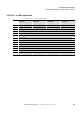
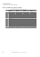
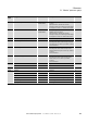
Table 22: Messages
Message
Possible causes and fixes
STOP Ready to start. There is no drive enable signal present. There are no fault messages present.
P-dEf The parameters‘ default settings have been loaded.
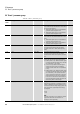
O-I Overcurrent at variable frequency drive output
Occurs right after switching on the unit:
• Check the cable connection between the variable frequency drive and the motor
• Check the motor for shorted turns and ground faults
Occurs when starting the motor:
• Check whether the motor can rotate freely and make sure that it is not being blocked mechanically.
• Motor with mechanical brake: Check whether the brake is being applied.
• Check the connection configuration (star/delta)
• Check to make sure that the correct rated motor current has been entered in P-08
• Increase the acceleration ramp time (t-acc, P-03) if necessary.
• Reduce the voltage boost with P-11.
Occurs during operation at a constant speed:
• Check whether the motor is overloaded.
Occurs during acceleration/deceleration:
• The ramp times are too short and require too much power.
If P-03 / P-04 cannot be increased, a larger device may be required.
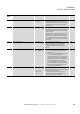
I.t-trP
Motor overload. The thermal protection mechanism has tripped as a result of the device being run above the rated
motor current set with P-08 longer than a specific time.
• Check to make sure that the rated motor current has been entered in P-08.
• Check the motor's connection configuration (e.g., start/delta)
• If the decimal points on the display flash during operation, this means that the unit is being run in its overload
range (> P-08). In this case, use P-03 to make the acceleration ramp longer or reduce the load.
• Check whether the motor is being blocked mechanically or whether there are any additional loads.
OI-b
Excessively high braking current
• Check the brake resistor and its wiring for short-circuits and ground faults.
• Make sure that the braking resistance value is not lower than the minimum permissible braking resistance.
OL-br Thermal overload on brake resistor. The drive has been switched off in order to prevent the brake resistor from being
thermally destroyed. This message will only be output if P-34 = 1 ("braking chopper")
• Make the P-04 and P-24 ramp times longer in order to have less frequent braking.
• Reduce the load's inertia (if possible).
If the protection achieved with P-34 = 1 is not adequate for the brake resistor being used:
• Provide external protection for the brake resistor and set P-34 to a value of 2.
PS-trp
Overcurrent (Hardware)
• Check the wiring to the motor and the motor itself for short-circuits and ground faults.
• Disconnect the motor cable from the variable frequency drive and switch the variable frequency drive back on.
• If the fault message still appears, the device needs to be replaced. Before commissioning the new device, check
the system for short-circuits or ground faults that could have caused the device to fail.
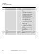
O.Volt
Overvoltage in DC link
• Check to make sure that the supply voltage falls within the range for which the variable frequency drive is sized.
If the error occurs during deceleration or stopping:
• Make the deceleration ramp (P-04/P-24) longer or use the brake resistor and activate the braking chopper with
P-34 (only on devices with frame size FS2, FS3, or FS4).