
User manual


5 Parameter
5.3 “Extended” parameter group
42 DC1 Variable Frequency Drives 11/16 MN04020004Z-EN www.eaton.com
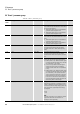
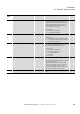
P-43 PID1 Mode 0, 1 PI(D) controller 1 mode
Possible values:
• 0: direct mode. This setting is used when an
increase of the feedback signal should lead to a
decrease of the motor speed.
• 1: inverse mode. If an increasing feedback
signal should increase the speed of the motor,
use inverse mode.
0
P-44 PID1 Set Point 1 Source 0, 1 Defines the set point source 1 of controller 1
Possible values:
• 0: digital set point signal, set with P-45
• 1: analog input 1
0
P-45 PID1 Set Point Digital 0, 1 Digital set point controller 1
Digital set point of the PI controller in case P44 = 0
0
P-46 PID1 Feedback 1 Source 0 - 5 Defines the feedback source 1 of controller 1
Possible values:
• 0: Analog-Eingang 2 (AI2)
• 1: Analog Input 1 (AI1)
• 2: motor current
• 3: DC-link voltage
• 4: difference AI1 - AI2
• 5: max value of AI1 and AI2
0
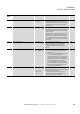
P-47 AI2 Signal Range 0 - 5 Configures the Analog input 2 for the selected
signal source type.
Possible values:
•0: 0 - 10 V
•1: 0 - 20 mA
• 2: t 4 - 20 mA (Trips in case of wire break)
• 3: r 4 - 20 mA (Ramps to f-fix1 (P-20) in case of
wire break)
• 4: t 20 - 4 mA (Trips in case of wire break)
• 5: r 20 - 4 mA (Ramps to f-fix1 (P-20) in case of
wire break)
0
P-48 t-Standby 0.0 - 25.0 s Time after which the drive changes to stand by
mode (inverter output disabled) when running at
min speed (f-min)
0: Standby mode disabled
non-zero: enter standby mode after the time
specified in this parameter.
Operation automatically resumes as soon as the
speed set point increases above P-02.
0.0 s
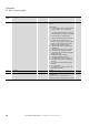
P-49 PID1 WakeUpLevel 0, 1 Wake-up level controller 1
Sets an error level (difference between the PID
reference and feedback values) above which the PID
controller will wake from Standby mode.
0
P-50 CAN0 Baudrate 0 - 3 CANopen Baudrate
Possible values:
• 0: 125 kbit/s
• 1: 250 kBit/s
• 2: 500 kbit/s
• 3: 1000 kbit/s
2
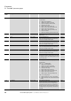
Para-
meter
Designation Value Description DS