
User manual


DC1 Variable Frequency Drives 11/16 MN04020004Z-EN www.eaton.com 1
Table of contents
0 About this manual ..................................................................... 3
0.1 Target group................................................................................. 3
0.2 List of revisions ............................................................................ 3
0.3 Writing conventions ..................................................................... 4
0.3.1 Hazard warnings of material damages ......................................... 4
0.3.2 Hazard warnings of personal injury .............................................. 4
0.3.3 Tips............................................................................................... 4
1 General........................................................................................ 5
1.1 Parameter Groups ........................................................................ 5
1.2 Menu structure ............................................................................ 6
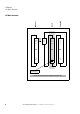
2 Control unit................................................................................. 7
2.1 Control unit elements................................................................... 7
2.2 Setting parameters....................................................................... 8
2.3 Resetting Parameters (RESET) .................................................... 8
2.4 Extended parameter set............................................................... 9
2.5 “Monitor” submenu..................................................................... 10
2.6 Control via keypad........................................................................ 11
3 Control signal terminals ............................................................ 12
3.1 Correspondence between inputs/outputs and terminals ............. 12
3.2 Configuration of the control signal terminals ............................... 16
3.2.1 P-12 = 0: Terminal-based operation ............................................. 16
3.2.2 P-12 = 1: digital setpoint value, 1 operating direction .................. 17
3.2.3 P-12 = 2: digital setpoint value, 2 operating directions ................ 18
3.2.4 P-12 = 3: Control via Modbus with internal acceleration and
deceleration ramps....................................................................... 19
3.2.5 P-12 = 4: Control via Modbus, ramps via Modbus....................... 20
3.2.6 P-12 = 5: PI controller .................................................................. 21
3.2.7 P-12 = 6: PI controller with AI1 totaling ....................................... 22
3.2.8 P-12 = 7: Control via CAN with internal acceleration and
deceleration ramps....................................................................... 23
3.2.9 P-12 = 8: Control via CAN, ramps via Modbus............................. 24
3.2.10 P-12 = 9: SWD control + setpoint value ...................................... 25
3.2.11 P-12 = 10: SWD control ............................................................... 26
3.2.12 P-12 = 11: SWD setpoint value.................................................... 27
3.2.13 P-12 = 13: SWD control + setpoint value, DI ENA....................... 28