INSTALLATION GUIDELINES Air-cooled Generators NOT INTENDED FOR USE IN CRITICAL LIFE SUPPORT APPLICATIONS. THIS PRODUCT CAN BE INSTALLED BY THE HOMEOWNER. HOWEVER, IF YOU ARE UNCOMFORTABLE WITH THE SKILLS OR TOOLS REQUIRED, HAVE A QUALIFIED ELECTRICIAN OR REFERENCE ALL APPROPRIATE DOCUMENTATION. THIS MANUAL SHOULD REMAIN WITH THE UNIT. Eaton Generator Support 1-800-975-8331 CONTRACTOR PERFORM THE INSTALLATION.
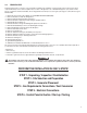
Table of Contents Frequently Asked Questions (FAQs) ......................................................................................................................................................... 1 Section 1 — Safety Rules & General Information ..................................................................................................................................... 2 1.1 Introduction.........................................................................................................
WARNING! California Proposition 65 Engine exhaust and some of its constituents are known to the state of California to cause cancer, birth defects, and other reproductive harm. WARNING! California Proposition 65 This product contains or emits chemicals known to the state of California to cause cancer, birth defects, and other reproductive harm.
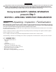
Section 1 Safety Rules & General Information 1.1 INTRODUCTION Thank you for purchasing this compact, high performance, air-cooled, engine-driven generator. It is designed to automatically supply electrical power to operate critical loads during a utility power failure. This unit is factory installed in an all-weather, metal enclosure that is intended exclusively for outdoor installation. This generator will operate using either vapor withdrawn liquid propane (LP) or natural gas (NG).
1.2 SAFETY RULES These Instructions – The manufacturer suggests that these rules for safe operation be copied and posted near the unit’s Save installation site. Safety should be stressed to all operators and potential operators of this equipment. Study these SAFETY RULES carefully before installing, operating or servicing this equipment. Become familiar with this Installation Manual and with the unit.
1.2.2 ELECTRICAL HAZARDS • All generators covered by this manual produce dangerous electrical voltages and can cause fatal electrical shock. Utility power delivers extremely high and dangerous voltages to the transfer switch, as does the standby generator when it is in operation. Avoid contact with bare wires, terminals, connections, etc., while the unit is running. Ensure all appropriate covers, guards and barriers are in place, secured and/or locked before operating the generator.
1.3.2 STANDARDS INDEX Applicable national, state or local laws, codes and regulations pertaining to the installation of engine-generator power systems must be strictly complied with. Always use the current acceptable version or edition of the applicable code or standard which applies to your jurisdiction. In the absence of pertinent local laws and standards, the following published booklets may be used as a guide (these apply to localities which recognize NFPA and IBC): 1. 2. 3. 4. 5. 6. 7. 8. 9. 10. 11.
a transfer switch. The transfer switch must effectively isolate the electrical system from the utility distribution system when the If this generator is used to power electrical load circuits normally powered by a utility power source, it is required by code to install generator is operating (NEC 700, 701 & 702).
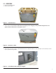
2.2 UNPACKING 1. Remove the cardboard carton. 2. Remove the wood frame. Figure 2.1 — Crated Generator 3. Remove bolts and clamps. Exercise caution when removing the generator. Dragging it off the pallet WILL damage the base. The generator must be lifted from the wooden pallet to remove. LID FRONT ACCESS PANEL REMOVE CRATING CLAMPS (4) Figure 2.2 — Generator on Pallet 4. The lid will be locked. A set of keys is located behind the breaker door. Open the breaker door and cut the zip tie to remove the keys.
5. There are two locks securing the lid, one on each side. To properly open the lid, press down on the lid above the side lock and unlock the latch. Repeat for the other side. If pressure is not applied from the top, the lid may appear stuck. NOTE: Always verify that the side locks are unlocked before attempting to lift the lid. 6. Once the lid is open, remove the front access panel by lifting it up and out. Also remove the black panel over top of the customer connection area. 7.
REMOTE MONITOR COVER PLATE 8-17 kW MAIN AC/CONTROL WIRING CONDUIT HOLE w/CAP PLUG 20 kW MAIN AC/CONTROL WIRING CONDUIT HOLE w/CAP PLUG FUEL CONNECTION HOLE BASE FACIA (IF EQUIPPED) Figure 2.6 — Generator Back View 2.
Section 3 Site Selection and Preparation 3.1 SITE SELECTION No operable windows or openings in the wall permitted within 5ft. (1.52m) from any point of the generator. 60in. (1524mm) 36in. (914mm) These guidelines are based upon fire testing of the generator enclosure and the manufacturer’s requirement for air flow for proper operation. Local codes may be different and more restrictive than what is described here. Existing Wall 18in. (457mm) Minimum Distance Top of Generator 36in. (914mm) 60in.
Install the generator set, in its protective enclosure, outdoors, where adequate cooling and ventilating air is always available (Figure 1.9). Consider these factors: • The installation of the generator must comply strictly with NFPA 37, NFPA 54, NFPA 58 and NFPA 70 standards. • Install the unit where air inlet and outlet openings will not become obstructed by leaves, grass, snow, etc. If prevailing winds will cause blowing or drifting, consider using a windbreak to protect the unit.
Figure 3.2 — Southwest Research Institute Decal (located inside the generator, next to the generator’s data decal) http://www.swri.org/4org/d01/fire/listlab/listprod/director.htm Based on this testing and the requirements of NFPA 37, Sec 4.1.4, the guidelines for installation of the generators listed above are changed to 18in. (457mm) from the back side of the generator to a stationary wall or building. For adequate maintenance and airflow clearance, the area above the generator should be at least 4ft. (1.
Figure 3.3 — Compacted Gravel Site Figure 3.4 — Concrete Pad Site After completing your SITE SELECTION and PREPARATION, time for Step 3: SECTION 4 - GENERATOR PLACEMENT Section 4 Generator Placement 4.1 GENERATOR PLACEMENT With the Site Selection and Preparation performed, proceed with placement and installation of the generator itself. All of the air-cooled generators come with a composite pad.
Figure 4.1 — Composite pad When mounting the generator to concrete, there are four mounting holes available for securing the generator, if codes require (two holes inside the front of the generator compartment and two holes in the back). See Figure 3.2. Figure 4.2 — Mounting Hole Location 4.1.1 FASCIA INSTALLATION (IF APPLICABLE) • Locate the four (4) threaded black rubber bumpers located in the Owner’s manual bag.
B A C Figure 4.3 — Facia Installation After completing GENERATOR PLACEMENT, proceed to Step 4: SECTION 5 — FUEL CONVERSION / GAS REQUIREMENTS / CONNECTIONS Section 5 Fuel Conversion / Gas Requirements / Connections 5.1 FUEL CONVERSION The generator was configured for natural gas operation at the factory. Switching over to LP Vapor is a simple procedure.
FUEL KNOB LOCATIONS SHOWN FROM GENERATOR AIR BOX SIDE VIEW 8 kW GENERATOR FUEL KNOB NG LP 11-20kW GENERATORS ORANGE FUEL CONVERSION KNOB FUEL KNOB Figure 5.1 — Fuel Conversion Knob Location for Single and Twin Cylinder Generators 5.2 FUEL REQUIREMENTS AND RECOMMENDATIONS With LP gas, use only the vapor withdrawal system. This type of system uses the vapors formed above the liquid fuel in the storage tank.
5.3 FUEL CONSUMPTION NOTE: Required fuel pressure for natural gas is 3.5-7” water column (7-13mm mercury). The required fuel pressure for LP Vapor is 10-12” water column (19-22mm mercury). These are approximate values, use the appropriate spec sheet or owner’s manual for specific values. Unit Nat. Gas LP Vapor 1/2 Load Full Load 1/2 Load Full Load 7 / 8 kW 78 / 2.21 121 / 3.43 0.87 / 3.29 1.42 / 5.37 10 / 11 kW 124 / 3.51 195 / 5.52 1.18 / 4.45 1.92 / 7.28 14 / 14 kW 177 / 5.01 279 / 7.
5.4.1 NATURAL GAS PIPE SIZING To properly use this chart, find the kW rating of the generator in the left column, and trace to the right. The number to the right is the maximum length (measured in feet / meters) allowed for the pipe sizes on top. The pipe sizes are measured by inside diameter (ID) to include any fittings, valves (must be full flow), elbows, tees or angles. Add 2.5ft. (.76m) per any bend, tee or angle in the pipe to the overall distance. kW 7-8 11 14 16-17 20 5.4.2 .75 / 19 55 / 16.
2. Most applications will require an external manual full flow shutoff valve on the fuel line. Figure 5.2 — Full Flow Shutoff Valve 3. When connecting the gas line to the generator, use the provided section of UL Listed or AGA-approved flexible fuel line in accordance with local regulations.
4. Never bend the flexible fuel line to avoid using an elbow. Bending the flexible line decreases its ability to absorb vibrations and defeats its purpose, as well as constricts the actual fuel flow. See Figure 5.5. 5. Check for leaks by spraying all connection points with a soap solution made of dishwashing soap and water. You should not see the solution be “blown away” or form “bubbles”. Next, check the gas pressure at the regulator in the generator by following these steps. – Close gas supply valve.
Primary Regulator Per LP Provider BTU and Pressure Decal Check Distance with LP Provider Size tank Large Enough to provide required BTUs for Generator and ALL Connected Appliance Loads. Be sure to correct for Weather Evaporation. Check distance with Regulator Manufacturer Fuel Tank Flex Fuel Line High Pressure Pipe sized per LP Provider Full Flow Safety Shut-off with Pressure Port Secondary-vented Regulator LP - BTU = Cubic feet/hour X 2500 Megajoules = Cubic meters/hour X 93.
6.2 CONTROL WIRING Control Wire Recommended Length and Size Maximum Wire Length Recommended Wire Size 1-115 ft (1-35 m) No. 18 AWG 116-185 ft (36-56 m) No. 16 AWG 186-295 ft (57-89 m) No. 14 AWG 296-460 ft (90-140 m) No.
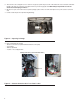
NOTE: Main AC wiring must be in accordance with local jurisdiction and codes. 6. 7. 8. 9. Strip the insulation off the wire ends. Do not remove excessive insulation. Remove the two cap plugs located behind the breaker door and to the right of the Main Breaker. Loosen the lugs of the Main Breaker through the access holes. Insert a power wire (E1 or E2) through the opening in the back cover and into the bottom lug. Torque to the proper specification.
With the ELECTRICAL CONNECTIONS completed, proceed to the final step - Step 6: SECTION 7 — CONTROL PANEL / ACTIVATION / START-UP / TESTING Section 7 Control Panel / Activation / Start-up / Testing 7.1 CONTROL PANEL INTERFACE 7.1.1 USING THE AUTO / MANUAL / OFF BUTTONS (FIGURE 7.1) the AUTO button pushed in, the engine may crank and start at any time without warning. Such automatic starting occurs when utility power source voltage droops below a preset level or during the normal exercise cycle.
Display Interface Menus The LCD display is organized as detailed below: • The “Home” page is the default page that will be displayed if no keys are pressed for five (5) minutes. This page normally shows the current Status message and the current date and time. The highest priority active Alarm and/or Warning will be automatically posted on this page as well, and the backlight will flash when such an event is detected. In the case of multiple Alarms or Warnings, only the first message will be displayed.
ACTIVATION CHART TROUBLESHOOTING Display Reads: Language English Use ARROW keys to scroll to desired language. Press ENTER to select. If the wrong language is chosen, it can be changed later using the “edit” menu. Press ENTER to begin the activation process. If ESCAPE is pressed instead of ENTER, the generator will only run in manual mode (for test purposes) and NOT ACTIVATED will be displayed. You will need to remove the 7.
7.3.1 Installation Assistant Interconnect System Self Test Feature (follow the on-screen prompts) Upon power up, this controller will go through a system self test which will check for the presence of utility voltage on the DC circuits. This is done to prevent damage if the installer mistakenly connects AC utility power sense wires into the DC terminal block. If utility voltage is detected, the controller will display a warning message and lock out the generator, preventing damage to the controller.
11. Connect the AC voltmeter test leads across terminal lugs E1 and neutral; then across E2 and neutral. In both cases, voltage reading should be 119-121 volts AC. If it’s not, verify that the MLCB is closed and verify AC output between the E1 and E2 of the MLCB and Neutral at the generator. Also, verify wiring from generator to E1, E2 ans Neutral lugs at transfer switch. 12. Set the generator’s main circuit breaker to its OFF (or OPEN) position. 13. Push the generator’s OFF button.
7.8 INSTALLATION SUMMARY 1. Ensure that the installation has been properly performed as outlined by the manufacturer and that it meets all applicable laws and codes. 2. Test and confirm proper operation of the system as outlined in the appropriate installation and owner’s manuals. 3. Educate the end-user on the proper operation, maintenance and service call procedures.
Section 8 Troubleshooting PROBLEM CAUSE CORRECTION The engine will not crank. 1. Fuse blown. 1. Correct short circuit condition by replacing 7.5 Amp fuse in generator control panel. 2. Loose, corroded or defective battery cables. 2. Tighten, clean or replace as necessary.* 3. Defective starter contact. 3. *See #2. 4. Defective starter motor. 4. *See #2. 5. Dead Battery. 5. Charge or replace battery. 1. Out of fuel. 1. Replenish fuel / Turn on fuel valve. 2. Defective fuel solenoid (FS).
Section 9 Quick Reference Guide Problem LED Things to Check Active Alarm Solution Unit running in AUTO but no power in house. GREEN Check MLCB. NONE Check MLCB. If it is in the ON position, contact the servicing dealer. Unit shuts down during operation. RED Check the LEDs / Screen for alarms. HIGH TEMPERATURE Check ventilation around the generator, intake, exhaust and rear of generator. If no obstruction, contact serving dealer. Unit shuts down during operation.
Section 10 Accessories There are performance enhancing accessories available for air-cooled generators. Accessory Description Cold Weather Kit Recommended in areas where temperatures regularly fall below 32º F (0º C). Scheduled Maintenance Kit Includes all pieces necessary to perform maintenance on the generator along with oil recommendations. Auxiliary Transfer Switch Lockout Enables any of the transfer switches to completely lock out one large electrical load by tying into its control system.
Section 11 Notes 33
34
35
T1 GROUNDING ELECTRODE CONNECTION (LOCATED ON THE REAR OF UNIT) N1 N2 0 194 23 WHITE T1 TOP VIEW N1 N2 0 194 23 GREEN E1 E2 NOTE: INSTALLATION MUST MEET ALL NATIONAL, STATE AND LOCAL ELECTRICAL CODES.
37 T1 GROUNDING ELECTRODE CONNECTION (LOCATED ON THE REAR OF UNIT) N1 N2 0 194 23 WHITE T1 TOP VIEW N1 N2 0 194 23 GREEN E1 E2 NOTE: INSTALLATION MUST MEET ALL NATIONAL, STATE AND LOCAL ELECTRICAL CODES.
© 2013 Eaton All rights reserved Specifications are subject to change without notice. No reproduction allowed in any form without prior written consent from Eaton. Internal Use Only – Not for Distribution Part No. 0J9944Y10 Rev. E (08/15/13) Printed in U.S.A.