
Owner`s manual

12
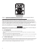
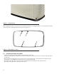
Figure 3.2 — Southwest Research Institute Decal (located inside the generator, next to the generator’s data decal)
http://www.swri.org/4org/d01/fire/listlab/listprod/director.htm
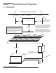
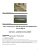
Based on this testing and the requirements of NFPA 37, Sec 4.1.4, the guidelines for installation of the generators listed above are
changed to 18in. (457mm) from the back side of the generator to a stationary wall or building. For adequate maintenance and airfl ow
clearance, the area above the generator should be at least 4ft. (1.22m) with a minimum of 3ft. (.91m) at the front and ends of the enclosure. This
would include trees, shrubs and vegetation shorter than 12in. (305mm) in height. Vegetation taller than 12in. (305mm) in height must have a
clearance of 60in. (1524mm). Vegetation not in compliance with these clearance parameters could obstruct air fl ow. In addition, exhaust fumes from
the generator could inhibit plant growth. See Figure 3.1 and the installation drawing within the owner’s manual for details.
Generator exhaust contains DEADLY carbon monoxide gas. This dangerous gas can cause unconsciousness or death. Do not place the unit near
windows, doors, fresh air intakes (furnaces, etc.) or any openings in the building or structure, including windows and doors of an attached garage.
If the generator is not set to the OFF mode, it can crank and start as soon as the battery cables are connected. If the utility power
supply is not turned off, sparking can occur at the battery posts and cause an explosion.
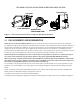
3.2 SITE PREPARATION
• Locate the mounting area as close as possible to the transfer switch and fuel supply.
• Leave adequate room around the area for service access (check local code), and place high enough to keep rising water from reaching the
generator.
• Choose an open space that will provide adequate and unobstructed airfl ow.
• Place the unit so air vents won’t become clogged with leaves, grass, snow or debris. Make sure exhaust fumes will not enter the building through
eaves, windows, ventilation fans or other air intakes (see the “Site Selection” section).
• Select the type of base, gravel or concrete, as desired or as required by local laws or codes. Verify your local requirements before selecting.
3.2.1 CRUSHED STONE OR GRAVEL
• Dig a rectangular area approximately 5in. (127mm) deep and about 6in. (152mm) longer and wider than the footprint of the generator. Cover with
polyurethane fi lm, if desired, and fi ll with pea gravel or crushed stone. Compact and level the stone. A concrete pad can be poured if desired or
required. The pad should be 4-5in. (102-127mm) thick and extend 6in. (152mm) beyond the outside of the generator in all directions.
NOTE: If a concrete pad is required, follow all applicable Federal, State or local codes.