
Owner`s manual


21
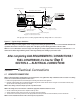
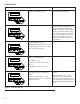
Size gas pipe from secondary regulator with Pipe Sizing Guide or to local codes.
Check Distance with LP Provider
Fuel Tank
Flex Fuel Line
High Pressure Pipe
sized per LP Provider
Check distance with
Regulator Manufacturer
Primary Regulator Per LP Provider
Full Flow Safety Shut-off
with Pressure Port
Size tank Large Enough
to provide required BTUs
for Generator and ALL
Connected Appliance
Loads. Be sure to correct
for Weather Evaporation.
LP - BTU = Cubic feet/hour X 2500
Megajoules = Cubic meters/hour X 93.15
Secondary-vented Regulator
BTU and Pressure Decal
Figure 5.7 — Typical LP Vapor Installation
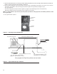
NOTE: When sizing a secondary regulator for LP or high pressure natural gas applications be sure to note the maximum individual load
capabilities which will be lower than total capacity. This could impact generator starting performance if sized too small.
NOTE: It is not recommended to reduce the fuel pipe size exiting the secondary regulator unless necessary to accommodate the ½” or ¾”
flexible fuel line that is shipped with the generator. This may potentially cause starting or performance issues.
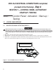
After completing GAS REQUIREMENTS / CONNECTIONS /
FUEL CONVERSION, it’s time for
Step 5:
SECTION 6 — ELECTRICAL CONNECTIONS
Section 6 Electrical Connections
6.1 GENERATOR CONNECTIONS
NOTE: Control wiring may be already wired on pre-wired generators. If so, tighten the 5’ whip conduit inside of the enclosure. If not, wiring
must be in accordance with local jurisdiction and codes.
1. Remove the appropriate Main AC/Control Wiring Knock-out Plug from the back of the generator.
2. Install the conduit and Main AC and Control Wires between the generator and the transfer switch. See Figure 2.6 for knockout locations (verify
specific transfer switch wiring/connections per model).
NOTE: These wiring connections may be present on pre-wired models.
NOTE: This wiring can be run in the same conduit if the appropriate insulation rated wire is used.
3. Seal the conduit at the generator and in compliance with any codes.
4. Strip the insulation from the ends of the wires. Do not remove excessive insulation.
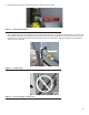
5. To connect the control wires, push down on the spring loaded connection point with a flat head screwdriver, insert wire and release.
NOTE: No wire insulation should be in the connection point, only bare wire.