
Owner`s manual


23
NOTE: Main AC wiring must be in accordance with local jurisdiction and codes.
6. Strip the insulation off the wire ends. Do not remove excessive insulation.
7. Remove the two cap plugs located behind the breaker door and to the right of the Main Breaker.
8. Loosen the lugs of the Main Breaker through the access holes.
9. Insert a power wire (E1 or E2) through the opening in the back cover and into the bottom lug. Torque to the proper specifi cation.
NOTE: There are 3 screws inside the top of the breaker panel (behind the breaker door). Removing these screws will allow the entire
breaker box to be carefully pulled out. When reinstalling, be certain that the tabs on the bottom lock into place.
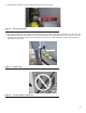
10. Connect the Neutral wire to the Neutral Lug and torque to the required specifi cation. See Figure 6.1.
11. Connect the Ground wire to the Ground Lug and torque to the required specifi cation. See Figure 6.1.
NOTE: Torque all wiring lugs, bus bars and connection points to the proper torque specifications. Torque specifications for the Main Line
Circuit Breaker (MLCB) can be found on a decal located on the inside of the Main Line Circuit Breaker Door.
6.4 BATTERY REQUIREMENTS
Group 26R, 12V, 525CCA (Minimum CCA)
6.5 BATTERY INSTALLATION
Fill the battery with the proper electrolyte fl uid if necessary and have the battery fully charged before installing it.
Before installing and connecting the battery, complete the following steps:
1. Verify that the generator has been turned OFF.
2. Turn off utility power supply to the transfer switch.
3. Remove the 7.5A fuse from the generator control panel.
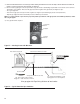
Battery cables were factory connected at the generator. See Figure 6.3. Connect cables to battery posts as follows:
4. Connect the red battery cable (from starter contactor) to the battery post indicated by a positive, POS or (+).
5. Connect the black battery cable (from frame ground) to the battery post indicated by a negative, NEG or (—).
6. Install the red battery post cover (included).
NOTE: Dielectric grease should be used on battery posts to aid in the prevention of corrosion.
NOTE: Damage will result if battery connections are made in reverse.
Figure 6.3 – Battery Cable Connections
NOTE: In areas where temperatures regularly fall below 32° F (0° C), it is recommended that a pad type battery heater be installed to aid
in cold climate starting. This is available as a cold weather kit through an authorized service dealer.