
Owner`s manual


27
7.3.1 Installation Assistant
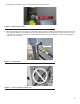
Interconnect System Self Test Feature (follow the on-screen prompts)
Upon power up, this controller will go through a system self test which will check for the presence of utility voltage on the DC circuits. This is done to
prevent damage if the installer mistakenly connects AC utility power sense wires into the DC terminal block. If utility voltage is detected, the controller
will display a warning message and lock out the generator, preventing damage to the controller. Power to the controller must be removed to clear this
warning.
Utility voltage must be turned on and present at the N1 and N2 terminals inside the generator control panel for this test to be performed and pass.
NOTE: The generator is to be run with all appropriate panels in place, including during troubleshooting by a technician.
7.3.2 Before starting, complete the following:
1. Ensure that the generator is OFF.
2. Set the generator’s main circuit breaker to the OFF (or OPEN) position.
3. Turn off all breakers that will be powered by the generator.
4. Check the engine crankcase oil level and, if necessary, fi ll to the dipstick FULL mark with the recommended oil. Do not fi ll above the FULL mark.
5. Check the fuel supply. Gaseous fuel lines must have been properly purged and leak tested in accordance with applicable fuel-gas codes. All fuel
shutoff valves in the fuel supply lines must be open.
During initial start up only, the generator may exceed the normal number of start attempts and experience an “overcrank” fault. This is due to
accumulated air in the fuel system during installation. Reset the control board by pushing the OFF button and ENTER key, and restart up to two
more times if necessary. If unit fails to start, contact a local dealer for assistance.
7.4 CHECK MANUAL TRANSFER SWITCH OPERATION
Refer to the “Manual Transfer Operation” section of the owner’s manual for procedures.
Do not attempt manual transfer switch operation until all power voltage supplies to the transfer switch have been positively turned
off. Failure to turn off all power voltage supplies will result in extremely hazardous and possibly fatal electrical shock.
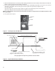
7.5 ELECTRICAL CHECKS
Complete electrical checks as follows:
1. Ensure that the generator is OFF.
2. Set the generator’s main circuit breaker to the OFF (or OPEN) position.
3. Turn OFF all circuit breakers/electrical loads that will be supplied by the generator.
4. Turn on the utility power supply to the transfer switch using the means provided (such as a utility main line circuit breaker).
The transfer switch is now electrically “hot.” Contact with “hot” parts will result in extremely hazardous and possibly fatal
electrical shock. Proceed with caution.
5. Use an accurate AC voltmeter to check utility power source voltage across transfer switch terminals N1 and N2. Nominal line-to-line voltage
should be 240 volts AC. If it’s not, verify AC output and wiring from utility source to N1 and N2 lugs at transfer switch.
6. Check utility power source voltage across terminals N1 and the transfer switch neutral lug; then across terminal N2 and neutral. Nominal line-to-
neutral voltage should be 120 volts AC. If it’s not, verify AC output and wiring from utility source to N1 and N2 lugs at transfer switch.
7. When certain that utility supply voltage is compatible with transfer switch and load circuit ratings, turn OFF the utility power supply to the transfer
switch.
8. On the generator panel, push the MANUAL button. The engine should crank and start.
9. Let the engine warm up for about fi ve minutes to allow internal temperatures to stabilize. Then, set the generator’s main circuit breaker to its ON
(or CLOSED) position.
Proceed with caution! Generator power voltage is now supplied to the transfer switch. Contact with live transfer switch parts will
result in dangerous and possibly fatal electrical shock.
10. Connect an accurate AC voltmeter and a frequency meter across transfer switch terminal lugs E1 and E2. Voltage should be 238-242 at a
frequency of 59.5-60.5 Hertz. If it’s not, verify that the MLCB is closed and verify AC output and frequency (Hertz or Hz) at the MLCB. Also verify
wiring from generator to E1 and E2 lugs at transfer switch.