
Information
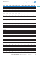
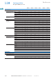
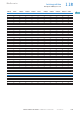
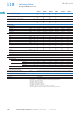
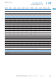
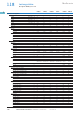
Table Of Contents

1/121Motoren schalten und schützen CA034001DE – Dezember 2017 www.eaton.eu
Leistungsschütze
Grundgeräte DILM(S) bis 170 A
1.18
Moeller series
1
DILM(S)7 DILM(S)9 DILM(S)12 DILM15 DILM(S)17 DILM(S)25 DILM(S)32 DILM38 DILM(S)40 DILM(S)50 DILM(S)65 DILM72 DILM(S)80 DILM(S)95 DILM(S)115 DILM(S)150 DILM170
Stromwärmeverluste (3-polig)
AC
DC
AC
DC
AC
DC
AC
DC
Stromwärmeverluste bei I
th
(60 °C) W 2,4
4,5
3
4,4
2,5
4,2
2,5
4
7,9 10,8 10,3 10,3 10,3 16,7 25,9 25,9 11,4 16,9 24,2 36,5 48,7
Stromwärmeverluste bei I
e
nach AC-3/400 V W 0,3 0,6
0,9
0,9
1,5
1,5
2,4
2,1 4,2 6,6 9,3 6,6 9,9 17,1 21 9 12,6 18,9 32,1 41,1
Impedanz pro Pol mΩ 2,5
4,6
2,5
4,6
2,5
4,6
2,5
4,6
2,7 2,7 2,7 2,7 1,9 1,9 1,9 1,9 0,6 0,6 0,6 0,6 0,6
Kraftantriebe
Spannungssicherheit
AC-betätigt Anzug x U
c
0,8 - 1,1 0,8 - 1,1 0,8 - 1,1 0,8 - 1,1 0,8 - 1,1 0,8 - 1,1 0,8 - 1,1 0,8 - 1,1 0,8 - 1,1 0,8 - 1,1 0,8 - 1,1 0,8 - 1,1 0,8 - 1,1 0,8 - 1,1 0,8 - 1,15 0,8 - 1,15 0,8 - 1,15
AC-betätigt Abfall x U
c
0,3 - 0,6 0,3 - 0,6 0,3 - 0,6 0,3 - 0,6 0,3 - 0,6 0,3 - 0,6 0,3 - 0,6 0,3 - 0,6 0,3 - 0,6 0,3 - 0,6 0,3 - 0,6 0,3 - 0,6 0,3 - 0,6 0,3 - 0,6 0,25 - 0,6 0,25 - 0,6 0,25 - 0,6
DC-betätigt
3)
Anzug x U
c
0,8 - 1,1
1)
0,8 - 1,1
1)
0,8 - 1,1
1)
0,8 - 1,1
1)
0,7 - 1,2
2)
0,7- 1,2
2)
0,7 - 1,2
2)
0,7 - 1,2
2)
0,7 - 1,2
2)
) 0,7 - 1,2
2)
0,7 - 1,2
2)
0,7 - 1,2
2)
0,7 - 1,2
2)
0,7 - 1,2
2)
0,7 - 1,2
2)
0,7 - 1,2
2)
0,7 - 1,2
2)
DC-betätigt
3)
Abfall x U
c
0,15 - 0,6 0,15 - 0,6 0,15 - 0,6 0,15 - 0,6 0,15 - 0,6 0,15 - 0,6 0,15 - 0,6 0,15 - 0,6 0,15 - 0,6 0,15 - 0,6 0,15 - 0,6 0,15 - 0,6 0,15 - 0,6 0,15 - 0,6 0,15 - 0,6 0,15 - 0,6 0,15 - 0,6
Leistungsaufnahme der Spule im kalten Zustand und 1,0 x U
c
50 Hz Anzug VA 24 24 24 24 52 52 52 52 149 149 149 149 310 310 180 180 180
50 Hz Halten VA 3,4 3,4 3,4 3,4 7,1 7,1 7,1 7,1 16 16 16 16 26 26 3,1 3,1 3,1
50 Hz Halten W 1,4 1,4 1,4 1,4 2,1 2,1 2,1 2,1 4,1 4,1 4,1 4,1 5,8 5,8 2,3 2,3 2,3
60 Hz Anzug VA 30 30 30 30 67 67 67 67 178 178 178 178 345 345 170 170 170
60 Hz Halten VA 4,4 4,4 4,4 4,4 8,7 8,7 8,7 8,7 19 19 19 19 30 30 3,1 3,1 3,1
60 Hz Halten W 1,4 1,4 1,4 1,4 2,1 2,1 2,1 2,1 4,1 4,1 4,1 4,1 5,8 5,8 2,3 2,3 2,3
50/60 Hz Anzug VA 27
25
27
25
27
25
27
25
62
58
62
58
62
58
62
58
168
154
168
154
168
154
168
154
372
328
372
328
– – –
50/60 Hz Halten VA 4,2
3,3
4,2
3,3
4,2
3,3
4,2
3,3
9,1
6,5
9,1
6,5
9,1
6,5
9,1
6,5
22
14
22
14
22
14
22
14
37,1
22,6
37,1
22,6
– – –
50/60 Hz Halten W 1,4
1,2
1,4
1,2
1,4
1,2
1,4
1,2
2,1 2,1 2,1 2,1 4,1 4,1 4,1 4,1 5,8 5,8 – – –
DC-betätigt Anzug W 2,6 4,5 4,5 4,5 12 12 12 12 24 24 24 24 90 90 149 149 149
DC-betätigt Halten W 2,6 4,5 4,5 4,5 0,9 0,9 0,9 0,9 1 1 1 1 1,5 1,5 1,9 1,9 1,9
Einschaltdauer % ED 100 100 100 100 100 100 100 100 100 100 100 100 100 100 100 100 100
Schaltzeiten bei 100 % U
c
(Richtwerte)
Hauptschaltglieder
AC-betätigt Schließzeit ms 15 - 21 15 - 21 15 - 21 15 - 21 16 - 22 16 - 22 16 - 22 16 - 22 12 - 18 12 - 18 12 - 18 12 - 18 14 - 20 14 - 20 28 - 33 28 - 33 28 - 33
Önungszeit ms 9 - 18 9 - 18 9 - 18 9 - 18 8 - 14 8 - 14 8 - 14 8 - 14 8 - 13 8 - 13 8 - 13 8 - 13 9 - 14 9 - 14 35 - 41 35 - 41 35 - 41
DC-betätigt Schließzeit ms 31 31 31 31 47 47 47 47 54 54 54 54 45 45 35 35 35
Önungszeit ms 12 12 12 12 30 30 30 30 24 24 24 24 34 34 30 30 30
Lichtbogenzeit ms 10 10 10 10 10 10 10 10 10 10 10 10 15 15 15 15 15
zulässiger Reststrom bei Ansteuerung von A1 - A2
aus der Elektronik (bei 0-Signal)
mA – – – – – – – – – – – – ≦ 1 ≦ 1 ≦ 1 ≦ 1 ≦ 1
Lebensdauer, mechanisch; Spule 50/60 Hz bei 50 Hz mechanische Lebensdauer bei 50 Hz ca. 30 % geringer als auf Seite 1/116 unter „Lebensdauer,
mechanisch AC-betätigt“ angegeben.
mechanische Lebensdauer bei 50 Hz ca. 30 % geringer als auf Seite 1/116 unter „Lebensdauer, mechanisch AC-betätigt“ angegeben.
Elektromagnetische Verträglichkeit (EMV)
Störaussendung nach EN 60947-1 nach EN 60947-1
Störfestigkeit nach EN 60947-1 nach EN 60947-1
Hinweise
1)
bei ...VDC: 0,85 - 1,1 nur mit Hilfsschalterbausteinen mit 3 oder mehr Önern
bei 24 V DC: 0,7 - 1,3 ohne Hilfsschalterbaustein und Umgebungstemperatur +40 °C
2)
RDC 12 (U
min
12 V DC/U
max
14 V DC)
RDC 24 (U
min
24 V DC/U
max
27 V DC)
RDC 60 (U
min
48 V DC/U
max
60 V DC)
RDC 130 (U
min
110 V DC/U
max
130 V DC)
RDC 240 (U
min
200 V DC/U
max
240 V DC)
Beispiel: U
s
= 0,7 x U
min
- 1,2 x U
max
/ U
s
= 0,7 x 24 V - 1,2 x 27 V DC
3)
mindestens geglättete Zweipulsbrückengleichrichter oder Drehstrom-Gleich richter