ENGLISH 5PX 5PX 5PX 5PX 5PX 5PX 5PX 5PX 1500i RT2U 2000i RT2U 2200i RT2U 3000i RT2U 3000i RT3U EBM 48V RT2U EBM 72V RT2U EBM 72V RT3U Installation and user manual Copyright © 2010 EATON All rights reserved.
Certification Standards UPS directives: pp Safety: IEC 62040-1: 2008 (C2) pp EMC: IEC 62040-2: 2005 pp Performance: IEC 62040-3: 2010 CE mark (EN 62040-1: 2008 and EN 62040-2: 2006 (C1)) Class B emission level CISPR 22: 2005 + A2 2006 (EN 55022) Harmonics emission: IEC 61000-3-2 edition 3.2: 2009 Flickers emission: IEC 61000-3-3 edition 2: 2008 The EC Declaration of Conformity is available upon request for products with a CE mark.
1. Introduction........................................................................................ 4 1.1 Environmental protection.................................................................................................4 2. Presentation....................................................................................... 5 2.1 2.2 2.3 2.4 2.5 2.6 Standard positions............................................................................................................5 Rear Panels.........
1. Introduction Thank you for selecting an EATON product to protect your electrical equipment. The 5PX range has been designed with the utmost care. We recommend that you take the time to read this manual to take full advantage of the many features of your UPS (Uninterruptible Power System). Before installing 5PX, please read the booklet presenting the safety instructions. Then follow the indications in this manual.
2.1 Standard positions Tower position D D W W H H Rack position D D H H W Description Weights (kg/lb) 5PX 1500i RT2U 5PX 2000i RT2U 5PX 2200i RT2U 5PX 3000i RT2U 5PX 3000i RT3U 5PX EBM 48V RT2U 5PX EBM 72V RT2U 5PX EBM 72V RT3U 27.60 / 60.90 28.50 / 62.80 28.50 / 62.80 38.08 / 84.00 37.33 / 82.30 32.80 / 72.30 46.39 / 102.30 44.26 / 97.60 614-07977-00_EN W Dimensions (mm/inch) DxWxH 522 x 441.2 x 86.2 / 20.6 x 17.4 x 3.4 647 497 522 647 497 x x x x x 441.2 441.2 441.2 441.2 441.
2. Presentation 2.
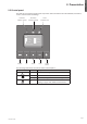
2.3 Control panel The UPS has a five-button graphical LCD. It provides useful information about the UPS itself, load status, events, measurements and settings. Power On Indicator (green) On battery Indicator (yellow) Alarm Indicator (red) Normal mode 100% 2.
2. Presentation 2.4 LCD description As default, or after 5 minutes of inactivity, the LCD displays the screen saver. The backlight LCD automatically dims after 10 minutes of inactivity. Press any button to restore the screen. Operation status Normal mode 100% 2.7kW 3kVA Load/equipment status 100% 17min 1EBM Battery status Efficiency: 98% Efficiency and load group information The following table describes the status information provided by the UPS Note.
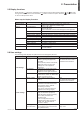
2.5 Display functions Press the Enter ( ) button to activate the menu options. Use the two middle buttons ( through the menu structure. Press the Enter ( ) button to select an option. Press the or return to the previous menu. and ) to scroll button to cancel Menu map for Display Functions.
2. Presentation Description Load segments - Auto shutdown delay Available settings [Disable] [0s] [1 s] [2 s]…[65354 s] During a power outage, authorises to keep some equipment running while turning off other equipment. This feature allows to save battery power. In/Out settings Overload pre[5 %] [10 %] [15 %] [20 %] ... [100 %] alarm [105 %] Gives a warning when a predefined critical percentage of load is reached. Cold start [Disable] [Enable] Authorises the product to start on battery power.
3.
3. Installation 3.2 Installation in tower position Note. The two supports for the tower position are used on the RT 2U version only. 3.3 Installation in rack position Follow steps 1 to 4 for module mounting on the rails. 1 1 2 3 3 4 4 The rails and necessary hardware are supplied by EATON.
3.4 Communication ports Connection of RS232 or USB communication port (optional) The RS232 and USB communication ports cannot operate simultaneously. 1. C onnect the RS232 (33) or USB (34) communication cable to the serial or USB port on the computer equipment. 2. C onnect the other end of the communication cable (33) or (34) to the USB (1) or RS232 (2) communication port on the UPS. The UPS can now communicate with EATON power management software.
3. Installation 3.5 Connection with a FlexPDU (Power Distribution Unit) module (optional) 1. 5 PX 2200i / 3000i: connect the UPS input socket (10) to the AC-power source using the cable (31) supplied. 5PX 1500i / 2000i: use the power cable of the protected equipment. 5PX 2. 5 PX 2200i / 3000i: connect the input socket on the FlexPDU module (50) to the UPS outlet (7) using the cable (43) supplied. 5PX 1500i / 2000i: connect the input socket on the FlexPDU module (50) to one of the outlets (9).
HotSwap MBP module operation The HotSwap MBP module has a rotary switch (55) with two positions: 53 54 Normal the load is supplied by the UPS, LED (53) is on. Bypass the load is supplied directly by the AC-power source. LED (54) is on. 55 UPS start-up with the HotSwap MBP module 1. Check that the UPS is correctly connected to the HotSwap MBP module. 2. Set switch (55) to Normal position. 3. Start the UPS by pressing the ON/OFF button on the UPS control panel. The load is supplied by the UPS.
4. Operation 4.1 Start-up and Normal operation To start the UPS: Verify that the UPS power cord is plugged in. The UPS front panel display illuminates and shows EATON logo. Verify that the UPS status screen shows . Press the button on the UPS front panel for at least 2 seconds. The UPS front panel display changes status to "UPS starting...". 5. Check the UPS front panel display for active alarms or notices. Resolve any active alarms before continuing. See "Troubleshooting" on page 18.
Low-battery warning pp The and indicator illuminates solid. pp The audio alarm beeps every three seconds. The remaining battery power is low. Shut down all applications on the connected equipment because automatic UPS shutdown is imminent. End of battery backup time pp LCD displays "End of backup time". pp All the LEDs go OFF. pp The audio alarms stops. 4.
5. Maintenance 5.1 Troubleshooting Operation status Batteries disconnected Possible cause The UPS does not recognise the internal batteries The batteries are disconnected Action If the condition persists, contact your service representative Verify that all batteries are properly connected. If the condition persists, contact your service representative. Overload Power requirements exceeds the UPS capacity (greater than 105 % of nominal) End of battery life The end of the battery life is reached.
5.2 Battery-module replacement Safety recommendations The battery can cause electrocution and high short-circuit currents. The following safety precautions are required before servicing the battery components: pp remove watches, rings, bracelets and all other metal objects from the hands and arms, pp use tools with an insulated handle. Battery-tray removal A - Remove the middle part. B-R emove the left-hand side of the front panel by pushing the button and then by sliding the part.
5. Maintenance Mounting the new battery module Carry out the above instructions in reverse order. pp To ensure safety and high performance, use only batteries supplied by EATON. pp Take care to firmly press together the two parts of the connector during remounting. 5.3 Maintenance on a UPS equipped with the HotSwap MBP module The HotSwap MBP module makes it 5PX possible to service or even replace the UPS without affecting the connected loads (HotSwap function). Maintenance 1.
6.
6. Appendices 6.2 Glossary Page 22 Backup time Time during which the load can be supplied by the UPS operating on battery power. Battery test Internal UPS test to check battery status. Cold start The devices connected to the UPS can be started even if AC input power is not available. The UPS operates on battery power alone. Deep discharge Battery discharge beyond the permissible limit, resulting in irreversible damage to the battery. FlexPDU Module with UPS outlets for installation in a bay.