3A74374H04 (I.B. 32-255-1J) Instructions for Installation, Operation and Maintenance of Type VCP-W Vacuum Circuit Breakers Effective 03/2013 Supersedes I.B.
3A74374H04 P a g e ii WARNING IMPROPERLY INSTALLING OR MAINTAINING THESE PRODUCTS CAN RESULT IN DEATH, SERIOUS PERSONAL INJURY, OR PROPERTY DAMAGE. READ AND UNDERSTAND THESE INSTRUCTIONS BEFORE ATTEMPTING ANY UNPACKING, ASSEMBLY, OPERATION OR MAINTENANCE OF THE CIRCUIT BREAKERS. INSTALLATION OR MAINTENANCE SHOULD BE ATTEMPTED ONLY BY QUALIFIED PERSONNEL. THIS INSTRUCTION BOOK SHOULD NOT BE CONSIDERED ALL INCLUSIVE REGARDING INSTALLATION OR MAINTENANCE PROCEDURES.
A74374H04 P a g e iii TABLE OF CONTENTS SECTION 1: INTRODUCTION 1-1 1-2 1-3 1-4 Page Preliminary Comments and Safety Precautions ..........................................................................................1 1-1.1 Warranty and Liability Information ......................................................................................................1 1-1.2 Safety Precautions ..................................................................................................................
3A74374H04 P a g e iv SECTION 5 DESCRIPTION AND OPERATION 5-1 5-2 5-3 5-4 5-5 5-6 5-7 5-8 5-9 Introduction ................................................................................................................................................23 Interrupter Assembly..................................................................................................................................23 5-2.1 Vacuum Interrupter ..........................................................................
3A74374H04 Page v FIGURES Figure Title Page 1-1 1-2 Type VCP-W and Type VCPW-SE Circuit Breaker Outlines and Dimensions in inches........................... 6 Type VCPW-ND Circuit Breaker Outlines and Dimensions in inches........................................................ 7 3-1 3-2 3-3 3-4 3-5 Typical VCP-W Tools and Accessories ...................................................................................................12 Typical Front View VCP-W Vacuum Circuit Breaker Element ..........
3A74374H04 P a g e vi TABLES Table Title Page 1.1 1.2 1.3 1.4 1.5 1.6 1.7 Type VCP-W Vacuum Circuit Breaker Through 15 kV Rated Symmetrical Current Basis ....................... 2 Type VCP-W Vacuum Circuit Breaker 27 kV Rated Symmetrical Current Basis ..................................... 3 Type VCP-W Extra Capability Vacuum Circuit Breaker 5-15 kV Rated Symmetrical Current Basis ........ 3 Type VCP-W Generator Vacuum Circuit Breaker 5-15 kV Rated Symmetrical Current Basis .................
3A74374H04 Page 9 SECTION 1: INTRODUCTION 1-1 PRELIMINARY COMMENTS AND SAFETY PRECAUTIONS This technical document is intended to cover most aspects associated with the installation, operation and maintenance of Type VCP-W, VCPW-SE, and VCPWND Vacuum Circuit Breakers. It is provided as a guide for authorized and qualified personnel only. Please refer to the specific WARNING and CAUTION in Paragraph 1-1.2 before proceeding past Section 1.
3A74374H04 P a g e 10 ADEQUATE MAINTENANCE. THIS INSTRUCTION BOOK MUST BE CAREFULLY READ AND FOLLOWED IN ORDER TO OBTAIN OPTIMUM PERFORMANCE FOR LONG USEFUL LIFE OF THE CIRCUIT BREAKER ELEMENTS. WITHIN THEIR NAMEPLATE RATINGS. OPERATION OUTSIDE OF THESE RATINGS MAY CAUSE THE EQUIPMENT TO FAIL, RESULTING IN DEATH, BODILY INJURY AND PROPERTY DAMAGE. WARNING ALL SAFETY CODES, SAFETY STANDARDS AND/OR REGULATIONS AS THEY MAY BE APPLIED TO THIS TYPE OF EQUIPMENT MUST BE STRICTLY ADHERED TO.
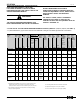
3A74374H04 P a g e 11 Table 1.2 (ANSI Standards) Type VCP-W Vacuum Circuit Breaker 27 kV Rated Symmetrical Current Basis Identification Circuit Breaker Type Rated Values Nominal Nominal Voltage 3-Phase Class MVA Class Voltage Insulation Level Current Maximum Voltage Withstand Test Voltage Range Voltage Factor Continuous Short Current Circuit at 60 Hz Current 3 Second Short time Current Carrying Capability I Power Impulse Frequency (1 Min.
3A74374H04 P a g e 12 Table 1.
3A74374H04 P a g e 13 Table 1.
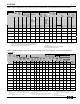
3A74374H04 P a g e 14 Table 1.8 (ANSI Standards) Type VCP-W ( K=1) Vacuum Circuit Breaker Through 15 kV Rated Symmetrical Current Basis (Standard Ratings) Identification Circuit Breaker Type Nominal Voltage Class Rated Values Voltage Maximum Voltage Range Voltage Factor Insulation Level Withstand Test Voltage Impulse Power Frequency (1 Min.) kV E kV rms K Current Continuous Short Current Circuit at 60 Hz Current (at Rated Max.
3A74374H04 P a g e 15 Table 1.9 (ANSI Standards) Type VCP-WXC Circuit Breaker Through 15 kV Rated Symmetrical Current (Standard Ratings) Basis See Page 40 (Figure 5-5A) for Control Schemes and Diagram that apply to this breaker. This Breaker differs from The Standard Breaker with the addition of a third motor cut-off switch and addition of two wires. Identification Circuit Breaker Type Rated voltage Voltage Max Voltage Voltage Range factor V K KV rms 150 VCP-WXC 63 E ff ec t iv e 0 3 / 1 3 17.
3A74374H04 P a g e 16 1-4 OUTLINES AND DIMENSIONS Breaker Identification A B C D E 240 VCP-W, 270 VCP-W & 270 VCP-WC 10 14 16.25 34.80 35.22 50/350, 50/350C, 150/1000, 150/1000C, 150/63, 3000A VCP-W, VCPW-SE,VCP-WC & VCP-W K=1>=50kA Except those immediately below 10 12 13.63 29.94 31.44 ALL All Other VCP-W,VCPW-SE & VCP-W K=1<=40kA including 50/25C & 150/75C, 1200A 10 12 13.63 29.81 29.
3A74374H04 Figure 1-2 Type VCPW-ND Circuit Breaker Outlines and Dimensions in inches E ff ec t iv e 0 3 / 1 3 P a g e 17
3A74374H04 P a g e 18 SECTION 2: SAFE PRACTICES 2-1 RECOMMENDATIONS Type VCP-W Vacuum Circuit Breaker Elements are equipped with high speed, high energy operating mechanisms. They are designed with several built-in inter-locks and safety features to provide safe and proper operating sequences.
3A74374H04 P a g e 19 SECTION 3: RECEIVING, HANDLING AND STORAGE 3-1 GENERAL Type VCP-W Vacuum Circuit Breaker Elements are subjected to complete factory production tests and inspection before being packed. They are shipped in packages designed to provide maximum protection to the equipment during shipment and storage and at the same time to provide convenient handling.
3A74374H04 3-5 TOOLS AND ACCESSORIES Tools and accessories, both standard and optional are available for use with the circuit breaker element (Figure 3-1). Spin-Free Levering-In Crank: Used to crank breaker between TEST and CONNECTED positions (Style 701B601G11). Standard Levering-In Crank: (Style 701B601G12). Maintenance Tool: Used to charge closing springs manually (Style 8064A02G11).
3A74374H04 Page 21 T able 3.2 V CP-W IEC Rated Break e r W eights Rating 36VCPW-ND25 36VCPW-ND32 72VCPW-ND25 72VCPW-ND32 36VCP-W25 36VCP-W32 36VCP-W40 72VCP-W25 72VCP-W32 72VCP-W40 120VCP-W25 120VCP-W32 120VCP-W40 175VCP-W25 175VCP-W32 175VCP-W40 240 VCP-W1 6 240 VCP-W20 40 VCP-W25 E ff ec t iv e 0 3 / 1 3 Normal Current Amperes Lbs.
3A74374H04 Page 22 Does not include shipping carton Figure 3-1 Typical VCP-W Tools and Accessories (Note: Products shown for representation only. New products may include design improvements and alternate nameplate configurations.
3A74374H04 Page 23 Figure 3-2 Typical Front View VCP-W Vacuum Circuit Breaker ( Newer model Breakers may not have the escutcheon as shown) E ff ec t iv e 0 3 / 1 3
3A74374H04 Figure 3-3 Typical VCP-W Vacuum Circuit Breaker Element with Front Cover Removed E ff ec t iv e 0 3 / 1 3 Page 24
3A74374H04 Figure 3-4 Typical Rear View VCP-W Vacuum Circuit Breaker Element E ff ec t iv e 0 3 / 1 3 Page 25
3A74374H04 Page 26 Figure 3-5 Typical VCP-W Vacuum Circuit Breaker Element Escutcheon ( Some Breakers may not have the escutcheon that is shown) E ff ec t iv e 0 3 / 1 3
3A74374H04 Page 27 SECTION 4: INITIAL INSPECTION AND INSTALLATION 4-4 INSULATION Check the circuit breaker’s primary and secondary insulation as described in Section 6. 4-1 INTRODUCTION 4-5 CONTACT EROSION AND WIPE WARNING BEFORE PLACING THE CIRCUIT BREAKER IN SERVICE, CAREFULLY FOLLOW THE INSTALLATION PROCEDURE GIVEN BELOW. NOT FOLLOWING THE PROCEDURE CAN FAIL TO UNCOVER SHIPPING DAMAGE THAT MAY RESULT IN INCORRECT CIRCUIT BREAKER OPERATION LEADING TO DEATH, BODILY INJURY, AND EQUIPMENT DAM-AGE.
3A74374H04 Page 28 4-8 ELECTRICAL OPERATION CHECK After having completed all previous checks and tests, the circuit breaker is ready to be operated electrically. It is preferred that this check be made with the circuit breaker in a TEST position or by using a test cable, if the circuit breaker is outside the cell structure. CAUTION BEFORE INSERTING THE CIRCUIT BREAKER EXAMINE THE INSIDE OF THE CELL STRUCTURE FOR EXCESSIVE DIRT OR ANYTHING THAT MIGHT INTERFERE WITH THE CIRCUIT BREAKER MOVEMENT.
3A74374H04 Figure 4-2 Typical VCP-W Circuit Breaker Compartment E ff ec t iv e 0 3 / 1 3 Page 29
3A74374H04 Page 30 To remove the circuit breaker from the structure, reverse the procedure just described by turning the levering-in crank in a counterclockwise direction. Keep in mind that safety interlocks may cause the circuit breaker to open and/or springs to discharge during the removal process. It depends on what condition the circuit breaker was in as removal began. For additional information on the levering mechanism, refer to paragraph 5-6 in this manual. 4-8.
3A74374H04 4-9 Page 31 CIRCUIT BREAKER/STRUCTURE INTERFACING WARNING NEVER DISABLE OR DEFEAT ANY INTERLOCKS. THEY ARE INTENDED FOR PROPER AND SAFE OPERATION. FAILURE TO COMPLY COULD RESULT IN DEATH, SEVERE PERSONAL INJURY AND/OR PROPERTY DAMAGE DUE TO THE HAZARDOUS VOLTAGE PRESENT. Type VCP-W Circuit Breakers are supplied with a series of interlocks to insure safe and proper interfacing between the circuit breaker and its compartment.
3A74374H04 Positive Interlock The positive interlock prevents the levering-in crank from being engaged if the circuit breaker is closed in the CONNECTED position. Negative Interlock The negative interlock prevents the circuit breaker from closing between the CONNECTED and TEST positions. Position Closing Interlock The circuit breaker is prevented from closing automatically when it is moved from the TEST to the CON NECTED position if the closing switch is maintained during the levering-in operation.
3A74374H04 Page 33 SECTION 5: DESCRIPTION AND OPERATION 5-1 INTRODUCTION Type VCP-W, VCPW-SE and VCPW-ND vacuum circuit breakers are horizontal drawout designs for use in metalclad switchgear compartments. Most ratings can be stacked two high in a vertical section resulting in a considerable savings of floor space. Vacuum interrupters are used with all circuit breakers to close and open the primary circuit.
3A74374H04 Page 34 are maintaining the adequate contact pressure to keep the contacts closed. Severe contact erosion would result in an unacceptable indication from the indicator (Figure 6-4). Depending upon the structural design, a small mirror may be required to inspect all three poles. Note that the actual configuration and/or appearance of the indicator can vary from one circuit breaker rating to another.
3A74374H04 Page 35 Table 5.1 VCP-W Circuit Bkr.Barrier Configurations ANSI BREAKER IDENTIFICATION AMPS REFERENCE VACUUM INTERUPTER DIAMETER-INCHES NUMBER OF BARRIERS VCP-W (K=1) Circuit Bkr.
3A74374H04 Page 36 WARNING DO NOT PLACE THE CIRCUIT BREAKER IN ITS COMPARTMENT WITHOUT THE PHASE BARRIERS IN PLACE. THE ABSENCE OF THE BARRIERS COULD CAUSE A CATASTROHIC FAILURE DURING INTERRUPTION OR OPERATION RESULTING IN DEATH, SEVERE PERSONAL INJURY AND/OR PROPERTY DAMAGE. The multiple finger primary disconnect contacts are silver plated and waxed.
3A74374H04 Figure 5-3 Closing Cam and Trip Linkage E ff ec t iv e 0 3 / 1 3 Page 37
3A74374H04 Figure 5-4 charging schematic E ff ec t iv e 0 3 / 1 3 Page 38
3A74374H04 a. b. c. d. Breaker element open, closing springs discharged Breaker element open, closing springs charged Breaker element closed, closing springs discharged Breaker element closed, closing springs charged 5-3.2 CHARGING Figure 5-4 is a schematic view of the spring charging parts of the stored energy mechanism.
3A74374H04 Figure 5-5 Typical VCP-W DC and AC Control Schemes E ff ec t iv e 0 3 / 1 3 Page 40
3A74374H04 Page 41 Figure 5-5A 15kV VCP-WXC 63kA 1200-3000A Special Power Plant Breakers, Styles: 4A35390G10, 4A35391G10, 4A35392G10 - DC Control Scheme and Diagram Note: This differs from the Standard VCP-W Breaker with the addition of a third motor-cut-off switch and two Additional wires. VCP-WXC VCP-WXC WARNING: 15kV VCP-WXC 63kA 1200-3000A Special Power Plant Breakers Styles: 4A35390G10, 4A35391G10, 4A35392G10 Circuit Breakers are configured for Power Plant specific Applications only.
3A74374H04 Page 42 Table 5.2 Circuit Breaker Timing Event Milliseconds (maximum) Closing Time (From Initiation of Close Signal to Contact Make) 45-60 Opening Time (Initiation of Trip Signal to Contact Break) 30-45 Reclosing Time (Initiation of Trip Signal to Contact Make) 140-165 been made while the circuit breaker is levered to the CONNECTED position. When the CS/C contact is made, the SR closes the circuit breaker.
3A74374H04 Figure 5-6 Undervoltage Trip Device Configuration E ff ec t iv e 0 3 / 1 3 Page 43
3A74374H04 5-5 INTERLOCKS AND INTERFACING Refer to Paragraph 4-9 of this manual for detailed information concerning circuit breaker interlocks and their interfacing with a switchgear structure compartment. In addition, refer to the instruction manual supplied with the switchgear assembly. Page 44 5-7 All circuit breakers are equipped with a mechanical operations counter. As the circuit breaker opens, the linkage connected to the pole shaft lever advances the counter reading by one (Figure 3-3).
3A74374H04 Page 45 SECTION 6: INSPECTION, MAINTENANCE AND TROUBLESHOOTING element annually or every 500 operations, which ever comes first. b. For special conditions such as frequent circuit breaker element operation, contaminated environments, and high temperature/humidity conditions, the inspection frequency should be a minimum of twice per year. 6-1 INTRODUCTION WARNING DO NOT WORK ON A BREAKER ELEMENT WITH PRIMARY POWER APPLIED.
3A74374H04 Page 46 considered to be qualified. Refer to further definitions in the National Electrical Safety Code. For the purpose of inspecting and maintaining such equipment, a qualified person must also be trained in regard to the hazards inherent to working with electricity and the proper way to perform such work. Such an individual should be able to de-energize, clear and tag circuits in accordance with established safety practices.
3A74374H04 Page 47 No./Section 1.Insulation Insulation Integrity 2. Power Elements 3.
3A74374H04 Page 48 6-4 VACUUM INTERRUPTER INTEGRITY TEST Vacuum interrupters used in Type VCP-W Vacuum Circuit Breaker Elements are highly reliable interrupting elements. Satisfactory performance of these devices is dependent upon the integrity of the vacuum in the interrupter and the internal dielectric strength. Both of these parameters can be readily checked by a one minute ac high potential test. Refer to Table 6.2 (page 31) for the appropriate test voltage.
3A74374H04 Page 49 Figure 6-2 Vacuum Interrupter Showing Contact Erosion Indicator with Breaker Open (Shown Here for Clarity Purposes Only) CAUTION SOME DC HIGH POTENTIAL UNITS, OPERATING AS UNFILTERED HALF-WAVE RECTIFIERS, ARE NOT SUITABLE FOR USE TO TEST VACUUM INTERRUPTERS BECAUSE THE PEAK VOLTAGE APPEARING ACROSS THE INTERRUPTERS CAN BE SUBSTANTIALLY GREATER THAN THE VALUE READ ON THE METER.
3A74374H04 Page 50 BLUE, RED OR BROWN CONTACT SPRINGS Figure 6-4 Wipe Indication Procedure (Performed Only with Breaker Closed) in service. If a solvent is required to cut dirt, use Stoddard’s Solvent Eaton 55812CA or commercial equivalent. Secondary control wiring also requires inspection for insulation damage. 6-7 INSULATION INTEGRITY CHECK Primary Circuit: The integrity of primary insulation may be checked by the 60Hz AC high potential test.
3A74374H04 Page 51 the voltage for one minute. Successful withstand indicates satisfactory insulation strength of the secondary control circuit. Remove the shooting wire and reconnect motor leads. 6-8 PRIMARY CIRCUIT RESISTANCE CHECK Since the main contacts are inside the vacuum chamber, they remain clean and require no maintenance at any time. Unlike many typical circuit breaker designs, VCP-W breakers do not have sliding contacts at the moving stem either.
3A74374H04 Page 52 CAN RESULT FROM CONTACT WITH ENERGIZED EQUIPMENT. ALWAYS VERIFY THAT NO VOLTAGE IS PRESENT BEFORE PROCEEDING WITH THE TASK, AND ALWAYS FOLLOW GENERALLY ACCEPTED SAFETY PROCEDURES. Safety Precautions: Read and understand these instructions before attempting any maintenance, repair or testing on the breaker. The user is cautioned to observe all recommendations, warnings and cautions relating to the safety of personnel and equipment.
3A74374H04 Figure 6-10 Attaching Closure Test Tool at HP Page 53 Figure 6-12 Manually Closing Circuit Breaker with Marker in Hole “C”. Step 5 - Mount the transparent CloSureTM Test Tool with two bolts and washers. Refer to Figures 6-19, 6-20 and Table 6.4 for appropriate mounting holes. Hand tighten the bolts (Figures 6-9, 6-10, 6-19 and 6-20). Step 6 - A Sanford® Sharpie® black fine point permanent marker, item no. 30001, is recommended for this next step.
3A74374H04 Page 54 Figure 6-15 Move Marker 15° to Left Figure 6-18 Illustrative Testing Tape Sample Step 12 - Inspect the circuit breaker to assure it is in the open position and the closing springs are discharged. Remove the transparent CloSureTM Tool. Remove the tape from the cam and stick the tape on the front right side sheet of the circuit breaker. Record the date of the test and the operations counter reading on the tape (Figures 6-16 and 6-17 and 6-18).
3A74374H04 Page 55 Breaker Line DHP-VR VCPW-ND VCP-W, VCP-WG, VCP-WGR VCP-WR W-VAC, W-VACR Approximate Mechanism Cabinet Width (inch) Upper Mounting Hole Lower Mounting hole Marker Placement Hole 20 29 20/21 29 33 A1 A1 A1 A1 A2 B2 B1 B2 B2 B2 C2 C5 C2 C5 C6 29 A1 B2 C5 18 20 29 18 25 33 A1 A1 A1 A1 A1 A2 B2 B2 B2 B2 B1 B2 C1 C2 C5 C1 C4 C6 Table 6.4 ClosureTM Tool Mounting/Testing Locations by Circuit Breaker Type relubricated.
3A74374H04 SYMPTOM Page 56 INSPECTION AREA PROBABLE DEFECTS Fails To Close • Closing Springs not charged •Control Circuit • Control Power (fuse blown or switch off) • Secondary Disconnects • Motor Cut-off Switch (Poor or burned contacts, Lever not operational) • Terminals and connectors (Poor or burned contacts) • Motor (Brushes worn or commutator segment open) • Mechanism • Pawls (Slipping or Broken) • Ratchet Wheel (Teeth worn or broken) • Cam Shaft Assembly (Sluggish or jammed) • Oscillator (Rese
3A74374H04 SYMPTOM Page 57 INSPECTION AREA PROBABLE DEFECTS Fails To Close • Closing Sound but no close • Pole Shaft (Not open fully) • Trip Latch Reset Spring (Damaged or Missing) • Trip Bar-D Shaft (Fails to remain reset) • Trip Latch-Hatchet (Fails to remain reset) • Trip Floor Tripper (Fails to remain reset) • Close Latch (Binding) • Close Latch Roller (Binding) • Trip Circuit Energized Undesirably Closes • Control Circuit • Close Circuit (CS/C Getting Shorted) • Mechanism • Close Release Latch
3A74374H04 Page 58 6-11 TROUBLESHOOTING CHART SYMPTOM INSPECTION AREA PROBABLE DEFECTS Fails To Trip • Trip Sound But No Trip • Trip Mechanism • Trip Bar, Trip Latch (Jammed) • Pole Shaft (Jammed) • Operating Rod Assembly (Broken or pins out) • Vacuum Interrupter (One or more Welded) Undesirably Trips • Control Circuit • Control Power (CS/T Switch, remains made) • Mechanism • Trip Coil Clapper (Not resetting) • Trip Bar or Trip Latch (Poor engagement of mating or worn surfaces) • Trip Bar Reset
3A74374H04 Page 59 7-1.1 ORDERING INSTRUCTIONS SECTION 7: RENEWAL PARTS 7-1 GENERAL In order to minimize production downtime, it is recommended that an adequate quantity of spare parts be carried in stock. The quantity will vary from customer to customer, depending upon the service severity and continuity requirements. Each customer should develop their own stock level based on operating experience. Refer to Tables 7.1 and 7.2 for guidance. a.
3A74374H04 Line No. 12 12A Description 75/500, 3000A-66kA 75VCP-W50C, 3000A Page 60 VCP-W Style Number VCPW-SE & 27kV VCPW-ND Qty.
3A74374H04 Line No. Description 28 29 29A 29B 29C 29D 29E 270/25, 630A-37kA 270/25, 1200A-37KA 270/25, 2000A-37kA 270/32, 1200A-50kA 270/32, 1200A-50kA 270/40, 1200A-64kA 270/40, 2000A-64kA Page 61 VCP-W Style Number VCPW-SE & 27kV VCPW-ND Qty .
3A74374H04 Page 62 7.1 Recommended Renewal Parts for ANSI Rated Breakers (Continued Next Page) Line No. 36 37 Description Up to 15kV, All 50/350, 150/1 000, 150/63 and 3000A Breakers VCP-W 691C648G01 27kV Style Number VCPW-SE & 27kV VCPW-ND 691C648G01 Qty .
3A74374H04 Page 63 7.1 Recommended Renewal Parts for ANSI Rated Breakers (Continued Next Page) Line No.
3A74374H04 Page 64 7.1 Recommended Renewal Parts for ANSI Rated Breakers (Continued Next Page) Line No. Description VCP-W Style Number VCPW-SE & 27kV VCPW-ND Qty. 65 65A Position Switch 1 Position Switch 2 8064A03G01 3759A93G01 699B147H01 3759A93H02 8064A03G01 3759A93G01 1 1 66 Auxiliary Switch 698B822H01 5697B02G01 5697B02G02 1 67 Trip D-Shaft 694C638G02 694C638G02 694C638G02 1 68 Main Link & Trip Latch 3A75675G01 3A75675G01 3A75675G01 1 69 Ground Contact Assy.
3A74374H04 Page 65 7.1 Recommended Renewal Parts for ANSI Rated Breakers VCP-W Style Number VCPW-SE & 27kV VCPW-ND Qt y. Fastener Kit 8061A01G01 8061A01G01 8061A01G01 1 Labels Kit 8295A45G04 8295A45G04 8295A45G04 1 Wiring Harness Repair Kit 691C281G01 691C281G01 691C281G02 Complete Replacement 691C281G03 691C281G07 (SE) 691C281G05 (27kV) 691C281G09 Line No.
3A74374H04 Page 66 7.1 Recommended Renewal Parts for ANSI Rated Breakers (Continued Next Page) Line No. Description Style Number VCP-WC Qty.
3A74374H04 Page 67 7.1 Recommended Renewal Parts for ANSI Rated Breakers Line No. Description Style Number VCP-WG Qty.
3A74374H04 Page 68 7.2 Recommended Renewal Parts for IEC Rated Breakers (Continued Next Page) Line No. Description Style Number Up to 17.5Kv 24Kv Qty.
3A74374H04 Page 69 20 21 120/40-1250A 120/40-2000A 8299A01H20 8299A01H21 3 3 22 23 175/25-1250A 175/25-2000A 8299A01H22 8299A01H23 3 3 24 25 175/32-1250A 175/32-2000A 8299A01H24 8299A01H25 3 3 26 27 175/40-1250A 175/40-1250A 8299A01H26 8299A01H27 3 3 28 29 29A 240/25-650A 240/25-1250A 240/25-2000A 8299A01H28 8299A01H29 8299A01H30 3 3 3 Primary Disconnects 30 31 Up to 175/40-630A Up to 175/40-1250A 699B104G01 699B104G01 6 6 7.
3A74374H04 Page 70 33 240/25-630A 699B352G01 6 34 34A 240/25-1250A 240/25-2000A 699B352G01 699B352G02 6 6 691C218H01 2 35 37 Phase Barrier Up to 175/40 240/25 691C176H04 Push Rod Assemblies 38 39 Up to 175/40-white springs Up to 175/40-Blue springs 40 240/25 41 Tie Bars Up to 175/40 E ff ec t iv e 0 3 / 1 3 691C650G01 691C651G01 3 3 691C241G01 3619A09H01 3 6
3A74374H04 Page 71 7.2 Recommended Renewal Parts for IEC Rated Breakers (Continued Next Page) Line No. Description Style Number Up to 17.
3A74374H04 Page 72 7.2 Recommended Renewal Parts for IEC Rated Breakers (Continued Next Page) Line No. Description Style Number Up to 17.
3A74374H04 Line No. Description 69 Ground Contact Assembly Page 73 Style Number Up to 17.
3A74374H04 Line No. Description 1 150VCP-WGC50 1200A E ff ec t iv e 0 3 / 1 3 Page 74 VCP-W 8297A36G28 Style Number W-VACW W-VACX Qty.
3A74374H04 Page 75 This instruction booklet is published solely for information purposes and should not be considered all inclusive. If further information is required, you should consult Eaton. Sale of product shown in this literature is subject to terms and conditions outlined in appropriate Eaton selling policies or other contractual agreement between the parties. This literature is not intended to and does not enlarge or add to any such contract.