UPS, PDU, RPP Submittal Project: Park Center Building A Submitted by: Capitol Power, Inc.
THIS PAGE INTENTIONALLY LEFT BLANK
Park Center Building A Bill of Materials Qty Description UPS 1 Eaton Power Xpert 9395-825 Model 825kVA N+1 UPS Output Rating: 825kVA (750kW at .91 lagging pf) N+1 UPM Complement: (4) 275kVA/250kW UPM's Input Voltage: 480VAC, 3 phase, 4 wire or 5-wire, Dual Feed Output Voltage: 480VAC, 3 phase, 4 wire or 5-wire Heat Rejection: 160,832 Btu/Hr Interruption Capacity: 100kAIC Max. Feeder Bkr: 1600A (80% Rated) Module Dimensions: 170" Wide, 32.7" Deep, 73.
Qty 1 Description Eaton Power Xpert 9395 Certified Factory Test Data Includes factory engineer certified written report from standard manufacturer factory test procedure.
Qty 2 Description Powerware 150kVA Power Distribution Unit Transformer Rating: 150kVA, k20, 150°C Rise, TP1 Cable Entry/Exit: Top or Bottom Distribution: (4) 225A Subfeed Breakers Monitoring: Eaton Subfeed Circuit Monitoring Communications: Power Xpert Gateway Card (SNMP, ModBus, TCP/IP) Features: Air Skirt Heat Rejection: 18,460 Btu/Hr PDU Dimensions: 39" Wide, 35" Deep, 80" High PDU Weight: 2,782 Pounds Embedded Warranty/Service Plan: Full 1-Year including parts, labor, and expenses 6 Powerware Remot
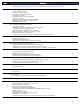
263353-3.6.D.3 - Equipment will be inspected to manufacturer's standard procedure only. 263353-3.6.D.6 - Site testing will be conducted using a resistive load bank and to manufacturer's standard procedure. 263353-3.6.E - Seismic restraint testing is responsibility of others. 263353-3.7 - 10 day performance testing is responsibility of others.
UPS
THIS PAGE INTENTIONALLY LEFT BLANK
Product brochure Power Xpert 9395 UPS 225–1100 kVA ™
The reliable solution Introduction and overview For more than 40 years, Eaton has been dedicated to delivering Providing high availability for your critical systems at all times, the the most technologically advanced products for our customers' 9395 was designed with numerous technological advancements mission-critical applications —a commitment exemplified by the THAT CREATE AN UNPRECEDENTED LEVEL OF RELIABILITY WHILE EMPHASIZING ® TM Power Xpert 9395 UPS.
!S AN EXAMPLE A LARGE DATA CENTER -6! WOULD REALIZE THE Measuring power performance: efficiency, power factor and THD following savings by using a 9395 with ESS compared to traditional .
9395 UPS Gets SMaRT ® Sync Control technology The 9395 UPS is the first power quality product to receive 3YNC #ONTROL ENSURES THAT THE OUTPUT OF TWO OR MORE SEPARATE a Sustainable Materials Rating Technology (SMaRT ) Gold UPSs (single modules or parallel systems) remain in phase with CERTIlCATION !S A RESULT THE 503 CAN CONTRIBUTE TO ,EADERSHIP one another so static transfer switches connected between the IN %NERGY AND %NVIRONMENTAL $ESIGN ,%%$ ) points for buildings separate distribution paths m
Easy Capacity Test The 9395 has the unique ability to test its entire power train As a result, they can produce a report that verifies these tests and under full load stress without the requirement of an external load. the overall performance of the UPS.
System Bypass Module: unparalleled flexibility for your parallel UPS system Four decades of experience in paralleling large UPS systems is 4HE %ATON 3"- INCORPORATES THE FOLLOWING HALLMARKS OF 0OWERWARE INCORPORATED IN THE 3YSTEM "YPASS -ODULE 3"- FROM %ATON &OR (OT 3YNC PARALLELING TECHNOLOGY WHICH HAS DElNED %ATON S MOST use with multi-module paralleled 9395 systems, the switchgear mission-critical UPS configurations for decades: ENCLOSURE ENCOMPASSES A CENTRALIZED STATIC SWITCH 9OU CAN ORDER it wi
825 kVA N+1: 9395 vs. Competitor Competitor solution 125 sq. ft. 19,215 lb system weight* Extensive site wiring *Excluding batteries AC Bypass AC Input Batt Dist 400 kVA Batt Dist 400 kVA Batt Dist Tie or SBM 400 kVA AC Input 9395 solution UPS Output AC Bypass 39 sq. ft.
Batteries: the heart of every UPS Service and support enhance performance When a utility power outage causes a UPS to switch to battery %ATON RECOGNIZES THAT SUPERIOR POWER RELIABILITY REQUIRES mAWLESS power, it's imperative that those batteries are healthy, charged and EXECUTION FROM OUR SERVICE TEAM )NCLUDED AT NO EXTRA CHARGE WITH UP TO THE TASK )MPROPER BATTERY MANAGEMENT IS THE NUMBER ONE every 9395 is: cause of downtime.
eNotify Remote Monitoring Service All PowerTrust Service Plans include Eaton’s eNotify Remote Monitoring Service, enabling Eaton service technicians to remotely monitor your UPS and batteries using one-way emails. With technical experts available to respond immediately and resolve MANY ISSUES REMOTELY E.
Monitoring, control and reporting capabilities Expanded solution: Ethernet connectivity ® The Power Xpert Gateway UPS card allows you to connect your 503 DIRECTLY TO YOUR %THERNET NETWORK AND THE )NTERNET 7ITH its built-in Web server it provides information on one or more UPS modules remotely, without additional software.
Core components UPM for redundancy or capacity Integrated System Bypass Module (ISBM) 275 kVA Uninterruptible Power Module (UPM) All components for redundant, multi-module UPS are included 9395 825 kVA N+1 or 1100 kVA capacity A closer look inside the 9395 Double-conversion topology converter/ inverter section ® X-Slot communications (4 slots) Redundant power supplies AC input and output connections Input circuit breaker option Redundant fans Top or bottom entry Static bypass (continuous duty)
Technical specifications General characteristics 2 Control panel (LCD) UPS rating (0.
CB1 (OPTION) UPM4 UPM3 UPM2 UPM1 MIS MBB BATTERY AC OUTPUT TO LOAD UPM4 kW 591 682 750 kVA 650 750 825 UPS Rating 480 480 480 VAC AC Input Voltage 480 480 480 VAC AC Output Voltage 1132 1029 892 992 902 782 AMP Nameplate Nameplate AMP Inverter AC Output Current Rectifier AC Input Current Product Specifications UPM1 UPM2 UPM3 kg(lbs) 3143 (6930) 3143 (6930) 3143 (6930) mm(in) 4308x874x1877 (169.6x34.4x73.9) 4308x874x1877 (169.6x34.4x73.9) 37.2 (126842) 42.
2 MAINTENANCE BYPASS SWITCHGEAR (OPTION) 1 AC OUTPUT TO LOAD Page: 1 of 4 A B C 8 7 6 5 UPM4 UPM3 UPM2 UPM1 CB1 (OPTION) ISBM UPS MODULE NK:K/(K7 ,"1K5*<," ,,<,<<*="3<<= = MIS MBB >?@@A BC BATTERY 4 3 2 1 EATON CORPORATION - CONFIDENTIAL AND PROPRIETARY NOTICE TO PERSONS RECEIVING THIS DOCUMENT AND/OR TECHNICAL INFORMATION THIS DOCUMENT, INCLUDING THE DRAWING AND INFORMATION CONTAINED THEREON, IS CONFIDENTIAL AND IS THE EXCLUSIVE PROPERTY OF EATON CORPORATION, AND IS MERELY ON
A 8 7 6 5 NK:K/(K7 ,"1K5*<," ,,<,<<*="3<<= = >?@@A BC 4 3 2 1 EATON CORPORATION - CONFIDENTIAL AND PROPRIETARY NOTICE TO PERSONS RECEIVING THIS DOCUMENT AND/OR TECHNICAL INFORMATION THIS DOCUMENT, INCLUDING THE DRAWING AND INFORMATION CONTAINED THEREON, IS CONFIDENTIAL AND IS THE EXCLUSIVE PROPERTY OF EATON CORPORATION, AND IS MERELY ON LOAN AND SUBJECT TO RECALL BY EATON AT ANY TIME.
A 8 7 6 5 NK:K/(K7 ,"1K5*<," ,,<,<<*="3<<= = >?@@A BC 4 3 2 1 EATON CORPORATION - CONFIDENTIAL AND PROPRIETARY NOTICE TO PERSONS RECEIVING THIS DOCUMENT AND/OR TECHNICAL INFORMATION THIS DOCUMENT, INCLUDING THE DRAWING AND INFORMATION CONTAINED THEREON, IS CONFIDENTIAL AND IS THE EXCLUSIVE PROPERTY OF EATON CORPORATION, AND IS MERELY ON LOAN AND SUBJECT TO RECALL BY EATON AT ANY TIME.
A 8 7 6 5 NK:K/(K7 ,"1K5*<," ,,<,<<*="3<<= = >?@@A BC 4 3 2 1 EATON CORPORATION - CONFIDENTIAL AND PROPRIETARY NOTICE TO PERSONS RECEIVING THIS DOCUMENT AND/OR TECHNICAL INFORMATION THIS DOCUMENT, INCLUDING THE DRAWING AND INFORMATION CONTAINED THEREON, IS CONFIDENTIAL AND IS THE EXCLUSIVE PROPERTY OF EATON CORPORATION, AND IS MERELY ON LOAN AND SUBJECT TO RECALL BY EATON AT ANY TIME.
THIS PAGE INTENTIONALLY LEFT BLANK
UPS INSTALLATION PLAN AND UNPACKING Table 3‐1.
UPS INSTALLATION PLAN AND UNPACKING CG CG Dimensions are in millimeters [inches]. Figure 3‐11. ISBM Section Center of Gravity – Momentary Static Switch CG Dimensions are in millimeters [inches]. Figure 3‐12. ISBM Section Center of Gravity – Continuous Static Switch Eaton 9395 UPS (450–825 kVA) Installation and Operation Manual 164201725 Rev 4 www.eaton.
UPS INSTALLATION PLAN AND UNPACKING CG CG Dimensions are in millimeters [inches]. Figure 3‐13. UPM Section Center of Gravity – Three UPM CG CG Dimensions are in millimeters [inches]. Figure 3‐14. UPM Section Center of Gravity – Two UPM 3-10 Eaton 9395 UPS (450–825 kVA) Installation and Operation Manual 164201725 Rev 4 www.eaton.
FIELD INSTALLED UPM INSTALLATION PLAN AND UNPACKING 1871.5 [73.7] CG CG 924 [36.4] 434 [17.1] 300 [11.8] 830 [32.7] 732 [28.8] Dimensions are in millimeters [inches]. Figure 3-6. FI−UPM Cabinet Center of Gravity 3.3 Inspecting and Unpacking the FI−UPM Cabinet The FI−UPM cabinet is palleted separately for shipping. The cabinet is shipped bolted to a wooden pallet and protected with outer protective packaging material (see Figure 3-7).
UPS INSTALLATION PLAN AND UNPACKING Table 3‐4.
UPS INSTALLATION PLAN AND UNPACKING Terminals E1A through E5A and E9A through E12A are stud type terminals. The intercabinet power wiring connections for this equipment are rated at 90°C. See Table 3‐9 for intercabinet power cable terminations and Table 3‐10 for supplied intercabinet wiring terminal hardware. The torque values listed in Table 3‐9 for the M8 studs are the maximum allowable. Tightening further will risk breaking or twisting the stud.
UPS INSTALLATION PLAN AND UNPACKING For a UPS with common rectifier input terminals, E1 through E12 are 2‐hole bus bar mountings for standard NEMA 2‐hole barrel lugs. The power wiring connections for this equipment are rated at 90°C. See Table 3‐11 for external power cable terminations, Table 3‐12 for supplied external wiring terminal hardware, and Table 3‐13 for recommended installation parts and tools not supplied by Eaton Corporation.
UPS INSTALLATION PLAN AND UNPACKING Table 3‐12.
UPS INSTALLATION PLAN AND UNPACKING Table 3‐15.
UPS INSTALLATION PLAN AND UNPACKING External overcurrent protection and disconnect are not provided by this product, but are required by codes. See to Table 3‐4 on page 3-14, Table 3‐5 on page 3-15, Table 3‐6 on page 3-16, Table 3‐7 on page 3-17 or Table 3‐8 on page 3-18 for wiring requirements. If an output lockable disconnect is required, it is to be supplied by the customer. Table 3‐16 lists the recommended rating for input circuit breakers.
UPS INSTALLATION PLAN AND UNPACKING CAUTION To reduce the risk of fire, connect only to a circuit provided with maximum input circuit breaker current ratings from Table 3‐16 in accordance with the NEC, ANSI/NFPA 70. The line‐to‐line unbalanced output capability of the UPS is limited only by the full load per phase current values for AC output to critical load shown in Table 3‐4 on page 3-14, Table 3‐5 on page 3-15, Table 3‐6 on page 3-16, or Table 3‐7 on page 3-17.
UPS SYSTEM INSTALLATION AC Input Breaker CB1 Phase A Phase B AC Output from UPMs (See Figure 4‐17 for detail.) Phase C Neutral from UPMs (See Figure 4‐17 for detail.) Phase C Phase B Phase A AC Input to UPMs (See Figure 4‐13 for detail.) DC Input to UPMs – (E5) (See Figure 4‐16 for detail.) DC Input to UPMs + (E4) (See Figure 4‐16 for detail.) Figure 4‐12.
UPS SYSTEM INSTALLATION UPM 4 (FI-UPM) UPM 1 Cable 1G1 & 1G2 Orange Phase A (E1A) UPM 2 Cable 2G1 & 2G2 Orange UPM 3 Cable 3G1 & 3G2 Orange (Not used with Two UPM systems.) UPM 1 Cable 1G1 & 1G2 Brown Phase B (E2A) UPM 2 Cable 2G1 & 2G2 Brown Phase B (E2A) UPM 4 (FI-UPM) UPM 3 Cable 3G1 & 3G2 Brown (Not used with Two UPM systems.) UPM 4 (FI-UPM) UPM 1 Cable 1G1 & 1G2 Yellow Phase C (E3A) UPM 2 Cable 2G1 & 2G2 Yellow UPM 3 Cable 3G1 & 3G2 Yellow (Not used with Two UPM systems.
UPS SYSTEM INSTALLATION Cable 1G3 Red UPM 1 (1E4A) + – Cable 1G3 Black Cable 1G3 Red UPM 2 (2E4A) + – + – Cable 2G3 Red Cable 3G3 Red UPM 3 (3E4A) UPM 1 (1E5A) Cable 2G3 Black Cable 2G3 Red + DC Input to UPMs Cable 1G3 Black Cable 3G3 Red (Not used with Two UPM systems.) Cable 2G3 Black UPM 2 (2E5A) Cable 3G3 Black UPM 3 (3E5A) Cable 3G3 Black (Not used with Two UPM systems.) Figure 4‐16.
UPS SYSTEM INSTALLATION Protective Cage Location of J50, J51, J61, and J70 Coiled Harnesses Wiring Access Location of P61 Harness Front Front UPM Wireway Location of P50, P51, and P70 Harnesses Location of RJ-45 Coiled CAN Cable A ISBM Section Right Side View B UPM Section Left Side View Figure 4‐18. UPS Intercabinet Interface Harness Locations Eaton 9395 UPS (450–825 kVA) Installation and Operation Manual 164201725 Rev 4 www.eaton.
UPS SYSTEM INSTALLATION Pl1 Interface Board Front ISBM Section Right Side Inside View Figure 4‐19. Pl1 Interface Board Location Pl1 Interface Board J39 Inverter CAN Connector Figure 4‐20. J39 Location on Pl1 Interface Board 4-22 Eaton 9395 UPS (450–825 kVA) Installation and Operation Manual 164201725 Rev 4 www.eaton.
UPS SYSTEM INSTALLATION Use the procedures in the following paragraphs to connect the external and battery power wiring. 4.8.1 2‐Hole Barrel Lug Terminations to Bus Bar Installation Paragraphs 4.8.2 and 4.8.3 require connecting input, output, and battery power wiring using 2-hole barrel lugs. See Figure 4‐21 for the hardware sequence when installing the lugs to the bus bars. Tighten the nut to the torque value listed in Table 3‐11.
UPS SYSTEM INSTALLATION Ventilation Grill Debris Shield (Remove shield before operating system.) ISBM Section Front Ventilation Grill Debris Shields (Remove shields before operating system.) Three UPM Section Front Ventilation Grill Debris Shields (Remove shields before operating system.) Two UPM Section Front Figure 4‐22. ISBM and UPM Section Debris Shields 4-26 Eaton 9395 UPS (450–825 kVA) Installation and Operation Manual 164201725 Rev 4 www.eaton.
UPS SYSTEM INSTALLATION Top Entry Conduit Landing for AC Input and Output, and DC Input (Remove panel to drill or punch conduit holes.) TOP VIEW Front Interface Entry Conduit Landings for TB1 through TB3 Wiring and X-Slot Connections (Remove panels to drill or punch conduit holes.) Front BOTTOM VIEW Bottom Entry Conduit Landing for AC Input and Output, and DC Input (Remove panel to drill or punch conduit holes.) Figure 4‐23.
UPS SYSTEM INSTALLATION AC Input to UPS Rectifier (A, B, C) (See Figure 4‐28 for Detail AA.) AC Input to UPS Bypass (A, B, C) (See Figure 4‐28 for Detail AA.) AC Output to Critical Load Phase C (E11) Phase B (E10) Phase A (E9) DC Input from Battery + (E4) (See Figure 4‐32 or Figure 4‐33 for Detail BB.) A B C DC Input from Battery – (E5) (See Figure 4‐32 or Figure 4‐33 for Detail BB.) N Neutral (E12) ISBM NOTE AC Input to Bypass terminals are not applicable to an IOM configuration. Figure 4‐27.
UPS SYSTEM INSTALLATION Ground Terminals Front ` Phase C (E3) Phase B (E2) AC Input to UPS Rectifier Phase A (E1) Phase A (E6) Phase B (E7) AC Input to UPS Bypass Phase C (E8) Section A–A Figure 4‐28. ISBM Section Power Terminal Detail AA – Common Rectifier Feed, Continuous Static Switch Eaton 9395 UPS (450–825 kVA) Installation and Operation Manual 164201725 Rev 4 www.eaton.
UPS SYSTEM INSTALLATION DC Input from Battery + (E4) Front DC Input from Battery – (E5) Section B–B Figure 4‐32. ISBM Section Power Terminal Detail BB – Common Battery 4-38 Eaton 9395 UPS (450–825 kVA) Installation and Operation Manual 164201725 Rev 4 www.eaton.
UPS SYSTEM INSTALLATION 11. Reinstall the front door removed in Step 3 and secure with the retained hardware. 12. Close the door and secure the latch. TB1 and TB2 (See Figure 4‐35 for detail.) X-Slot Communication Bays (See Figure 4‐40 on page 4-47 for detail.) TB3 (See Figure 4‐37 on page 4-44 for terminal assignments.) ISBM Figure 4‐34. ISBM Section Interface Terminal Locations Eaton 9395 UPS (450–825 kVA) Installation and Operation Manual 164201725 Rev 4 www.eaton.
UPS SYSTEM INSTALLATION Table 4‐1.
UPS SYSTEM INSTALLATION X-Slot Communication Bays TB1 See Figure 4‐37 for terminal assignments. TB2 Figure 4‐35. Interface Terminal Detail TB2 3 Alarm Relay NC 4 Alarm Relay Common 5 Alarm Relay NO 6 Alarm Relay Common Alarm Relay NOTE NOTE NOTE NOTE Alarm relay contacts have a maximum current rating of 5A and a switched voltage rating of 30 Vac and 28 Vdc. Alarm relay normally-open and normally-closed return terminals are separated on the terminal board but are electrically in common.
UPS SYSTEM INSTALLATION UPS REPO NC REPO Return REPO NO REPO Return 1 Battery Aux Battery Aux Common Battery Shunt Trip +Battery Shunt Trip – Output Contactor K3 NC Aux Output Contactor K3 NC Aux Common TB1 10 1 Pull Chain Pull Chain Common Alarm Relay NC Alarm Relay Common Alarm Relay NO Alarm Relay Common TB2 10 UPS 1 TB3 10 Building Alarm 1 Building Alarm 1 Return Building Alarm 2 Building Alarm 2 Return Building Alarm 3 Building Alarm 3 Return Building Alarm 4 Building Alarm 4 Return Buildi
UPS SYSTEM INSTALLATION Battery Disconnect UPS TB1 Battery Aux 5 Battery Aux Common 6 48 Vdc Battery Shunt Trip + 7 48 Vdc 48 Vdc Battery Shunt Trip – ST 8 NOTE Battery aux and DC shunt trip wiring should be a minimum of 18 AWG. Figure 4‐38.
UNDERSTANDING UPS OPERATION AC Input to Bypass 3 or 4 Wire A-B-C Rotation AC Input to UPS Rectifier 3 Wire A-B-C Rotation A Single-Feed Kit (Not supplied with the UPS) Input Breaker (CB1) (optional) Input Contactor (K1) Fuse Rectifier Fuse Fuse Fuse Fuse Fuse Inverter Output Contactor (K3) Input Contactor (K1) Rectifier Fuse Inverter X-Slot Interface Backfeed Contactor (K5) Input Contactor (K1) Fuse Battery Converter Static Switch Fuse Fuse Fuse Alarm Relays Interface Board Recti
UPS OPERATING INSTRUCTIONS Control Panel AC Input Breaker CB1 (Optional) (Not available with separate rectifier feed option) ISBM Figure 7‐2. UPS Controls and Indicators – Continuous Static Switch 7.1.1 Control Panel The control panel is used to set up and control the UPS, and to monitor UPS operation. For a description of the UPS control panel functions, see paragraph 7.2. 7.1.2 Circuit Breakers Optional circuit breaker (CB1) is used to control the AC input to the UPS rectifier.
UPS MAINTENANCE Do not dispose of batteries in a fire. Batteries may explode when exposed to flame. Do not open or mutilate batteries. Released electrolyte is harmful to the skin and eyes. It may be toxic. 9.2 Performing Preventive Maintenance The UPS system requires very little preventive maintenance. However, the system should be inspected periodically to verify that the units are operating normally and that the batteries are in good condition. 9.2.
UPS MAINTENANCE Middle Right ISBM Air Filter Bottom Left ISBM Air Filters Bottom Right ISBM Air Filters Figure 9‐2. ISBM Section Air Filter Locations – Continuous Static Switch 9-4 Eaton 9395 UPS (450–825 kVA) Installation and Operation Manual 164201725 Rev 4 www.eaton.
UPS MAINTENANCE UPM Air Filters Figure 9‐4. Three UPM Section Air Filter Locations 3. If the UPS is a Plus 1 or a two UPM model, check the Field Installed UPM (FI-UPM) air filter (located behind the front panel) and wash or replace as necessary. See Figure 9‐5 for the filter location. The FI-UPM filter size is 20” 44” 0.25”. Contact an Eaton service representative for a replacement filter. To remove the filter: a.
UPS MAINTENANCE FI-UPM Air Filter Figure 9‐5. FI-UPM Air Filter Location 9.2.3 PERIODIC Maintenance Periodic inspections of the UPS should be made to determine if components, wiring, and connections exhibit evidence of overheating. Particular attention should be given to bolted connections. Maintenance procedures should specify that the bolted connections be retorqued to values listed in this manual. 9.2.
THIS PAGE INTENTIONALLY LEFT BLANK
Eaton Power Xpert Architecture Eaton Power Xpert Gateway UPS Card Features/benefits s Web-enabled monitoring of power quality data - Data can be viewed from any location with a Web browser s Data, event and system logging with time stamp Accurate logging for power quality analysis, log files can be exported in a CSV format to Excel to help generate reports s Modbus TCP/IP and SNMP v3 Support - Open communication protocol facilitates integration with standard building management systems and network manageme
Technical specifications The Power Xpert Gateway UPS Card kit includes the following: Local Configuration Cable Web browsers supported IE 7 and 8 Quick Start Guide Mozilla Firefox 2.0 and higher Power Xpert Gateway UPS Card Google Chrome Ordering information Catalog number PXGXUPS Physical characteristics Dimensions 12 cm x 11.4 cm x 3.9 cm (4.7” x 4.5” x 1.
Remote monitoring of temperature, HUMIDITY AND USER SUPPLIED CONTACT DEVICES PowerChain Management solutions Eaton Environmental Monitoring Probe Product Snapshot Type: Environmental monitoring device Package Contents: Main unit, User's guide, Double-sided Velcro tape Compatibility: 10/100Mb ConnectUPS-X, ConnectUPS-BD and ConnectUPS-E with FW V3.01 and higher Dimensions (LxWxH): 2.26 x 1.48 x 1.15 (inches) 57.6 x 37.6 x 29.
Hot-pluggable and seamless integration with ConnectUPS Web Cards UPS ID View UPS model, firmware, location, etc. details Current Status Metering Details Measures humidity, temperature and two additional user-supplied contact devices (rear door entry, smoke detection etc.
120 VAC 120 VAC ESA5010 ESA5011 20mA 20mA Standby 50mA 70mA Alarm CAPABILITIES AND LIMITATIONS OF SMOKE ALARMS SAFETY TIPS WHERE TO LOCATE SMOKE ALARMS NFPA RECOMMENDATIONS LOCATIONS TO AVOID INSTALLATION AND TESTING MAINTENANCE AND TROUBLESHOOTING LIMITED WARRANTY ASI Electronics smoke alarms are designed to provide early warning of fire and smoke at reasonable cost. Early warning can mean the difference between a safe escape and no escape at all.
THIS PAGE INTENTIONALLY LEFT BLANK
UPS REMOTE MONITOR PANEL
THIS PAGE INTENTIONALLY LEFT BLANK
USING FEATURES AND OPTIONS 10.3 Optional Remote Monitor Panel As an option, a Remote Monitor Panel (RMP) can be installed to monitor the operation of the UPS system from virtually any location within the facility, up to 152.4m (500 ft) from the UPS. The RMP contains backlit status indicators and a local horn. The RMP can be flush‐mounted or surface‐mounted on a desktop, or secured to a wall. Figure 10‐1 shows an RMP. Figure 10‐1.
USING FEATURES AND OPTIONS The RMP contains a local horn and the backlit status indicators listed in Table 10‐1. Table 10‐1. RMP Status Indicators SYSTEM NORMAL The UPS is energized (either with utility power or battery backup) and is supplying conditioned power to the critical load. NO REDUNDANCY This indicator applies only to parallel systems when one cabinet is not functioning. ON GENERATOR The UPS input and bypass are being supplied by the power from the genera tor instead of from the utility power.
Installation Information 16. Conduit must be installed between the UPM cabinets for parallel interface wiring. Install the interface wiring in separate conduit from the power wiring. 17. Use Class 1 wiring methods (as defined by the NEC) for parallel interface wiring. The wire should be shielded twisted pair, rated for 5 amps maximum. 18. See Table X and Chapter 6 for Powerware Hot Sync CAN Bridge Card interface wiring. Table X.
Installation Information 19. Conduit must be installed between the UPS cabinet and the RMP II, RIM II, or SCM II for signal wiring. Conduit must be installed between the device and the power source for power wiring. Install the signal wiring in separate conduit from the power wiring. 20. Conduit and wiring between the UPS and the RMP II, RIM II, or SCM II is to be supplied by the customer. 21. Maximum distance between the UPS cabinet and RMP II, RIM II, or SCM II is not to exceed 500 feet. 22.
INSTALLATION INFORMATION KNOCKOUTS PROVIDED ON FIVE SURFACES FLUSH MOUNT USE #10 PAN HEAD SCREWS (MOUNT WITH VENT HOLES FACING UP) SURFACE MOUNT USE #10 PAN HEAD SCREWS (FOR HANGING) (MOUNT WITH VENT HOLES FACING UP) DESCRIPTION: L REMOTE MONITOR PANEL (RMP) OPTIONAL DRAWING NO: Dimensions are in millimeters [inches] REVISION: SHEET: 164201604-11 A DATE: 1 of 1 091505 EATON Powerware® 9390 UPS (100–160 kVA) Installation and Operation Manual 164201604 Rev D www.powerware.
SEISMIC DATA REQUIREMENTS FOR EATON UPS EQUIPMENT INSTALLATION 1.10 9395 Foundation Plan and Mounting Requirements Proper mounting of the equipment is the single most important factor in withstanding a seismic event. The foundation must be level and continuous under the entire assembly. The foundation must be designed to withstand the reaction loads imposed on it by the equipment during a seismic event.
SEISMIC DATA REQUIREMENTS FOR EATON UPS EQUIPMENT INSTALLATION 1.11 Displacement The horizontal displacement of the top of the equipment is listed in Table H. The horizontal displacements given in Table H are plus/minus values. The equipment must be at the minimum distance listed in Table H to avoid contact with other stationary objects during a seismic event. Table H.
SEISMIC DATA REQUIREMENTS FOR EATON UPS EQUIPMENT INSTALLATION Figure 1‐17. 9395 1100 kVA UPS or 825 kVA +1 UPS Seismic Mounting Dimensions Figure 1‐18.
SEISMIC DATA REQUIREMENTS FOR EATON UPS EQUIPMENT INSTALLATION Figure 1‐21.
SEISMIC DATA REQUIREMENTS FOR EATON UPS EQUIPMENT INSTALLATION I/O Cabinet Right Side Figure 1‐22.
SEISMIC DATA REQUIREMENTS FOR EATON UPS EQUIPMENT INSTALLATION Figure 1‐23. 9395 FI-UPM Shim Location Detail for Seismic Kit Front Front FI-UPM Right Side I/O Cabinet Right Side Figure 1‐24.
THIS PAGE INTENTIONALLY LEFT BLANK
SPARES
THIS PAGE INTENTIONALLY LEFT BLANK
9395-275kVA UPM 400/480VAC Spares Kit Level "D" Kit 106711270 PART NUMBER 128304134-008 128307025-004 128307027-001 151101091-001 DESCRIPTION FUSE, 3.
9395-825kVA ISBM 480VAC Spares Kit Level "D" Kit 106711285 PART NUMBER 101073677-002 1028553 101073914 129400075 3989190 P-151000014 128307029-002 128304134-008 1030951 DESCRIPTION 9395 ISBM MCU Power Supply Thyristor Module 800A 1600V 9395 Mini CSB Board Thermal Interface Pad Silicone Thermal Compound Fan, 172x150x51mm, 403cfm, 48V Fuse, 2000A Fuse, 3A 9395 PCBAS Control Board II U/M EA EA EA EA EA EA EA EA EA QTY 1 4 1 10 1 1 6 6 1
MBP
THIS PAGE INTENTIONALLY LEFT BLANK
THIS PAGE INTENTIONALLY LEFT BLANK
BATTERY
THIS PAGE INTENTIONALLY LEFT BLANK
Available exclusively from EnerSys ®, the world leader in stored power solutions.
1. Insulating covers with voltmeter probe access enhance safety and simplify maintenance routines 2. Integrated handle support doubles as an automatic spacer between units to enhance airflow and thermal management 3. Nord-Lock® washer provides a secure terminal connection over the life of the battery 4. Solid tin-plated copper busbars reduce connection resistance to enhance power delivery from the battery system 5. Dual-tab washer enables quick connection to battery monitoring systems 6.
DataSafe® 16V batteries save valuable space EnerSys® engineers set out to develop a true UPS design, front-terminal battery that would be cost effective, space efficient, and easy to maintain. It also had to be conducive to incorporating monitoring systems, adaptable to existing cabinet designs, and built on proven electrochemistry and design practices. Finally, the battery had to be capable of scaling to larger capacities to minimize the number of strings in larger UPS systems.
General Specifications Inches W 4.6 7.0 7.0 L 27.2 27.2 27.2 16HX550F-FR 16HX800F-FR 16HX925F-FR H 12.3 12.3 12.3 L 692 692 692 Millimeters W 117 177 177 H 313 313 313 Internal Resistance (mΩ) Weight Lbs 151 232 248 Weight kg 68.5 105.2 112.
3. INSPECTION UPON RECEIPT OF GOODS 3.1 General Special precautions and care have been taken to ensure the cabinet system arrives safe and undamaged. However, upon receipt, you should inspect the entire shipment, including the crate and any boxes for evidence of damage that may have occurred during transit. 3.
TM Power/Full SolutionsTM Publication No. US-HXFTCAB-IM-001 July 2009 23 www.enersys.
TM Power/Full Solutions TM Publication No. US-HXFTCAB-IM-001 July 2009 24 www.enersys.
TM Power/Full Solutions TM Publication No. US-HXFTCAB-IM-001 July 2009 25 www.enersys.
K Z' ![ \ ! !]!K & ' ! =! =!? @ !^_` *{ K & ' !^ { + '! < = ! # $ & '! * > !? @ *& =!^ Z| { =!? @ _ } ? @ _ } ? @ $OO!~DOXHV!OLVWHG!DUH!IRU!WKH!XQLW !KH!QRPLQDO!$+
K Z' ![ Z \ ! !]! '= !KY } !` !^_` *!*
BATTERY MONITOR
THIS PAGE INTENTIONALLY LEFT BLANK
PowerChain Management Solutions Eaton Cellwatch Battery Monitoring System .
Cellwatch Battery Monitoring System Businesses that rely on technology for their day-today operations cannot afford to risk even a split second of downtime, let alone an extended outage. To keep information technology, telecommunications, factory floor and call center operations running smoothly, businesses have to take a close look at their power infrastructure to identify vulnerabilities and take action to prevent costly downtime. Central to an effective power infrastructure are UPSs.
Battery status at a glance Cellwatch gives you a simple view of the battery with clear indications of a good or bad cell or jar, including the cells on your generator batteries. Ohmic value history A rapid rise in the cell or jar's ohmic value indicates cell failure. /HMIC VALUE OF FAILING CELLS CAN RISE TO TWICE ITS NORMAL VALUE WITHIN days. At this point your battery may be compromised and immediate action is required.
Cell voltage performance on load Battery current over time Cellwatch automatically monitors discharges and can track over 1900 readings a minute. This capability provides the data for a very detailed map of individual cell or jar performance on load. Cellwatch shows you how much current the batteries are taking during normal float charge. An increase in current could indicate a problem.
Fast installation—immediate results Cellwatch’s modular format allows for easy installation and expandability. Its layout design minimizes wiring on the battery, increasing reliability and ease-of-installation. Cellwatch uses optical fiber that reduces electrical noise that can negatively impact battery performance.
Specifications Data Collection Module Control Unit Voltage measuring characteristics Operating Specifications Ambient operating temperature Storage temperature Power supply Power supply range Power supply frequency Power supply rating 0°C to 50°C/32°F to 122°F 10°C to 80°C/50°F to 17°F Manually switchable 110 Vac or 230 Vac 80 Vac to 135 Vac 160 Vac to 270 Vac 50 Hz to 60 Hz Max 5 VA (15 mA quiescent current) Voltage measuring range 2ESOLUTION Accuracy Protection Transient suppression pulses non repeti
SITE TESTING
THIS PAGE INTENTIONALLY LEFT BLANK
Start-Up Scope of Work Attachment L-2 This scope of work is shared by UPS, Eaton DC, Eaton PDU/PDR/RPP/STS, Flywheel, Non Eaton UPS and Distributed Bypass. The following is an outline of general procedures and tests, if applicable, that are normally performed by Field Service Personnel during the course of a standard start-up for new units or to recertify and restart a previously started UPS. All checks and processes may not be applicable to all equipment models. UPS/PDU/RPP/STS START-UP PROCEDURE 1.
6. BATTERY SET-UP 6.1. Determine common or separate battery set-up process and settings 6.2. Check for proper cell interconnections with respect to polarity throughout battery. 6.3. Check battery configuration matches required unit configuration (voltage, polarity, number of cells per string) 7. BRANCH CIRCUIT MONITORING SET-UP (if optionally purchased) 7.1. Ensure installation configuration matches application 7.2. Perform branch circuit breaker scheduling 7.3. Check voltage and current calibrations 8.
1.1. Check internal power connections in Flywheel module for tightness while observing proper safety precautions 1.2. Check all control wiring terminations and plugs in Flywheel module for tightness and/or proper setting 1.3. Check to see that all subassembly heat sinks are secure 1.4. Verify bearing and hardware installation 2. ELECTRICAL PRE-CHECK 2.1. Check Flywheel system for grounds 2.2. Check DC bus for short circuits 2.3. Check power terminations for proper voltages 2.4.
THIS PAGE INTENTIONALLY LEFT BLANK
Park Center Building A: UPS Load Bank Test Procedure Eaton will provide a load bank with cable, test equipment (Fluke 87III or equivalent, Fluke i410 Amp lamp or equivalent, Fluke 123 Oscilloscope or equivalent, and laptop with service tool) and a Field engineer to load bank test the UPS System. The customer is responsible to have a qualified electrician on site during the testing and to connect and disconnect the load bank to the UPS System.
snapshot). E. Battery Discharge Testing (at owner’s discretion) Manufacturer shall verify the operation of the Battery Systems x Visual inspection of battery jars and enclosures for evidence of physical x damage, leaking, corrosion, overheating, arcing, or burning. x Perform a partial battery discharge test on UPS battery system under full load x conditions. (5 Minute discharge) x Verify operation of Battery Notices and Alarms F.
50kVA PDU
THIS PAGE INTENTIONALLY LEFT BLANK
0OWER QUALITY SOLUTIONS Power Distribution Unit Front and rear access 4HE %ATON LINE OF THREE PHASE POWER DISTRIBUTION UNITS 0$5S PROVIDE ROBUST POWER DISTRIBUTION THAT CAN BE EASILY TAILORED TO MEET THE DESIGN SPECIFICATIONS OF ANY FACILITY OR DATA CENTER 4HE 0$5 OFFERS RATINGS FROM TO K6! AND + AND + TRANSFORMERS INCLUDING 40 EFFICIENCY %NERGY -ANAGEMENT 3YSTEM %-3 OFFERS COST EFFECTIVE INTELLIGENCE TO MANAGE LOAD EFFICIENCY Easy Service and Setup Reduce installation time and save on s
TECHNICAL SPECIFICATIONS1 Category Up to 150 kVA 200-300 kVA ELECTRICAL CHARACTERISTICS kVA Input Ratings Output Ratings 50 / 75 / 100 / 125 / 150 208V - 3 Phase, 4 Wire + Ground Frequency T Transformer T Type TTransformer Characteristics Transformer T Compensation Taps T 200 / 225 / 300 208 / 380 / 400 / 415 / 480 / 600V - 3 Phase, 3 Wire + Ground (Single & Dual Input) Dual Input: Basic or Premium5 60 Hz Copper / Double Shielding / Class R (220°C) Insulation 150°C Temp. Rise / K13 (Std.
Installation Reference Table B.
Installation Reference The PDU cooling requirements are shown in Table D. Table D. PDU Cooling Requirements During Full Load Operation Rating Voltage Heat Rejection kVA K-factor Input Output Watts BTU/hr Kg-cal/hr 50 13 208 208/120 1118 3814.77 961.31 50 13 480 208/120 2018 6885.70 1735.17 50 20 480 208/120 2020 6892.53 1736.89 75 13 208 208/120 2640 9008.05 2269.99 75 13 480 208/120 3415 11652.46 2936.37 75 20 480 208/120 2214 7554.48 1903.
Installation Reference Table J.
Installation Reference as Table O.
Installation Reference Table S.
THIS PAGE INTENTIONALLY LEFT BLANK
ED AS LE RE Date PDF Generated:8/15/2011 Page: 1 of 5
ED AS LE RE Date PDF Generated:8/12/2011 Page: 1 of 1
Installation Reference Lightning Arrestor (optional) SPD (optional) Optional Unmonitored Subfeed Breakers (See Figure A-44 for details.) AC Input (Single Input) (A, B, C) (See Figure A-41, Figure A-42, or Figure A-43 for details.) Unmonitored Subfeed Output Neutral Terminals AC Output (A, B, C) (Same for Right Side.) (See Figure A-44 for details.
Installation Reference Phase A AC Input to Main Breaker CB1 or CB2 Phase B Phase C Figure A-41. Power Terminal Locations – “F” Frame PDU Input Main Breaker CB1 or CB2 Terminal Detail Phase A AC Input to Main Breaker CB1 or CB2 Phase B Phase C Figure A-42. Power Terminal Locations – “K” Frame PDU Input Main Breaker CB1 or CB2 Terminal Detail Phase A AC Input to Main Breaker CB1 or CB2 Phase B Phase C Figure A-43.
Installation Reference Phase A AC Output to Critical Load Phase B Phase C Figure A-44. Power Terminal Locations – “F” Frame Output Subfeed Breaker Terminal Detail A.6 Interface Wiring Notes Control wiring for features and options should be connected at the customer interface terminal blocks located inside the PDU. WARNING Do not directly connect relay contacts to the mains related circuits. Reinforced insulation to the mains is required.
Installation Reference Table U. UCB TB1 and TB2 Interface Connections TB1 Terminal Name Description 1 Building Alarm 1 2 Building Alarm 1 Return Input: Programmable PDU alarm, activated by a remote dry contact closure. Building alarm inputs can be programmed for use with either normally-open or normally-closed contacts.
Installation Reference Optional Aux and Shunt Trip Terminal Blocks for PRL3 and Unmonitored Subfeed Breakers. See Figure A-48 for details. X-Slot Communication Bay Terminals TB1 and TB2 (See Figure A-54 for details.) UCB Figure A-46. PDU Interface Terminal Locations for Two PRL3 and Subfeed Breaker Monitoring A-56 Eaton PDU (150 kVA) Installation and Operation Manual 164202126—Rev 5 www.eaton.
Installation Reference TB1 1 Building Alarm 1 Building Alarm 1 Return UCB Building Alarm 2 Building Alarm 2 Return REPO REPO Return Local EPO (factory wired) 1 Alarm Relay Common Alarm Relay NO Alarm Relay NC 3 8 Local EPO Return (factory wired) TB2 NOTE All building alarm inputs require an isolated normally-open or normally-closed contact or switch (rated at 24 Vdc, 20 mA minimum) connected between the alarm input and common terminal as shown.
Installation Reference A.10 Optionall Air Skirt An air skirt can be installed around the perimeter of the PDU Main Unit and any sidecars installed with the PDU. An air skirt helps contain air flow under the PDU. See Figure A-63 through Figure A-68 for air skirt installation illustrations. CAUTION Use air skirts only when the PDU is installed on a raised floor where the raised floor acts as a plenum and provides adequate air flow to the PDU.
Installation Reference Base Mounting Screws (10 places) Corner Screws (4 places) Figure A-66. Air Skirt Footprint for 150 kVA PDU Base Mounting Screws (18 places) Corner Screws (4 places) Figure A-67. Air Skirt Footprint for 150 kVA PDU with Front-Facing Sidecars Eaton PDU (150 kVA) Installation and Operation Manual 164202126—Rev 5 www.eaton.
Power quality solutions Eaton Energy Management System Features s #ONTINUOUSLY MONITORS POWER CONDITIONS AT BRANCH CIRCUIT SUB FEED AND MAIN BREAKER LEVELS s )SSUES WARNINGS AND ALARMS IF CURRENT LOADS OR ENVIRONMENTAL CONDITIONS EXCEED USER DEFINED THRESHOLDS s 4RACKS EVENT HISTORY WITH INTEGRATED REAL TIME CLOCK FOR TIME STAMPING s #OLLECTS DATA FROM UP TO EIGHT PANELBOARDS AND POLE POSITIONS IN A SINGLE SYSTEM s -AKES ALL DATA AVAILABLE ON A STATE OF THE ART LOCAL DISPLAY s 3ENDS DATA TO REMOTE DISP
The architecture of the monitoring system is straightforward, which makes it stable and reliable. Branch circuit wires are threaded through current transducers (CTs), which sense the current level going through the wire and send the information to a universal controller. CTs are also used for sub-feed and main breakers. The controller assimilates the information from CTs at multiple panelboards and then relays it to a local display or remote management system for analysis and reporting.
A unique, differentiating feature of the Energy Management System is its ability to archive data and perform load profiling across many months. The information captured from each branch circuit and the main incoming/outgoing circuits is stored on the local PDU control board. An on-board, real-time clock accurately time-stamps all events. All the information can be sent over the LAN to your building management system.
Technical Specifications General UL and cUL listed Up to 252 branch circuits monitored on a single display Input Monitoring Three-phase voltage: RMS L-L, RMS L-N, RMS %, THD % and frequency Three-phase current: RMS, RMS %, THD %, Crest Factor Power: kW, kVA, PF (when input CT option is installed) Monthly profiling: Time-stamped Min V, Max V, Min I, Max I, Max THD, Min kVA, Max kVA, Power Factor Active alarms and event logging: Input ACUV, Input ACOV, Input UFOF, Input Phase Rotation, Input Phase Loss, THD O
Power Quality solutions ® Power Xpert Gateway PDP Card Monitoring energy in a networked world The Power Xpert Gateway PDP card (PXGX PDP) is the primary data acquisition solution for Eaton power distribution units (PDUs) remote power panels (RPPs), rack power modules (RPMs), power distribution racks (PDRs), and energy management system upgrade kits (EMSs). Data from the downstream devices are time stamped and stored in nonvolatile memory.
Remotely configure and edit panel and breaker settings from your desk Improve productivity with Eaton’s ability to remotely configure or edit panel and breaker settings in your PDU, RPP or RPM with the on-board configuration pages that guide you through the process. Additionally, the ‘Save and Restore’ feature provides an effective method to reproduce the configuration if needed at a later time.
QuickServer QuickServer Gateway QuickServer is a high performance, fully configurable, cost effective Building and Industrial Automation gateway for integrators to easily interface devices to networks in commercial buildings and industrial plants. System integrators world-wide have benefitted from the value of the powerful line of interoperability gateways offered by FieldServer Technologies.
QuickServer Specifications Field Connections 1. TX/Rx/GND 2. +/-/Frame Ground 3. See Manual 4. 10/100 Base T 5. FTT10 6. KNX/EIB TP1 Environment o o Operating temperature: -40 to 75 C (-40 to 167 F) Relative humidity: 5-90% RH non-condensing Power Requirements 9-30 VDC or 12-24 VAC Current draw @ 12V ♦ FS-QS-1010, FS-QS-12X0: 150 mA ♦ FS-QS-1011, FS-QS-12X1: 279 mA Physical Dimensions (HxWxD) 4.5 x 2.9 x 1.6 in. (11.5 x 7.4 x 4.1 cm) 0.4 lbs (0.
150kVA PDU
THIS PAGE INTENTIONALLY LEFT BLANK
0OWER QUALITY SOLUTIONS Power Distribution Unit Front and rear access 4HE %ATON LINE OF THREE PHASE POWER DISTRIBUTION UNITS 0$5S PROVIDE ROBUST POWER DISTRIBUTION THAT CAN BE EASILY TAILORED TO MEET THE DESIGN SPECIFICATIONS OF ANY FACILITY OR DATA CENTER 4HE 0$5 OFFERS RATINGS FROM TO K6! AND + AND + TRANSFORMERS INCLUDING 40 EFFICIENCY %NERGY -ANAGEMENT 3YSTEM %-3 OFFERS COST EFFECTIVE INTELLIGENCE TO MANAGE LOAD EFFICIENCY Easy Service and Setup Reduce installation time and save on s
TECHNICAL SPECIFICATIONS1 Category Up to 150 kVA 200-300 kVA ELECTRICAL CHARACTERISTICS kVA Input Ratings Output Ratings 50 / 75 / 100 / 125 / 150 208V - 3 Phase, 4 Wire + Ground Frequency T Transformer T Type TTransformer Characteristics Transformer T Compensation Taps T 200 / 225 / 300 208 / 380 / 400 / 415 / 480 / 600V - 3 Phase, 3 Wire + Ground (Single & Dual Input) Dual Input: Basic or Premium5 60 Hz Copper / Double Shielding / Class R (220°C) Insulation 150°C Temp. Rise / K13 (Std.
Installation Reference Table B.
Installation Reference The PDU cooling requirements are shown in Table D. Table D. PDU Cooling Requirements During Full Load Operation Rating Voltage Heat Rejection kVA K-factor Input Output Watts BTU/hr Kg-cal/hr 50 13 208 208/120 1118 3814.77 961.31 50 13 480 208/120 2018 6885.70 1735.17 50 20 480 208/120 2020 6892.53 1736.89 75 13 208 208/120 2640 9008.05 2269.99 75 13 480 208/120 3415 11652.46 2936.37 75 20 480 208/120 2214 7554.48 1903.
Installation Reference Table J.
Installation Reference as Table O.
Installation Reference Table S.
THIS PAGE INTENTIONALLY LEFT BLANK
ED AS LE RE Date PDF Generated:8/15/2011 Page: 1 of 5
ED AS LE RE Date PDF Generated:8/12/2011 Page: 1 of 1
Installation Reference Lightning Arrestor (optional) SPD (optional) Optional Unmonitored Subfeed Breakers (See Figure A-44 for details.) AC Input (Single Input) (A, B, C) (See Figure A-41, Figure A-42, or Figure A-43 for details.) Unmonitored Subfeed Output Neutral Terminals AC Output (A, B, C) (Same for Right Side.) (See Figure A-44 for details.
Installation Reference Phase A AC Input to Main Breaker CB1 or CB2 Phase B Phase C Figure A-41. Power Terminal Locations – “F” Frame PDU Input Main Breaker CB1 or CB2 Terminal Detail Phase A AC Input to Main Breaker CB1 or CB2 Phase B Phase C Figure A-42. Power Terminal Locations – “K” Frame PDU Input Main Breaker CB1 or CB2 Terminal Detail Phase A AC Input to Main Breaker CB1 or CB2 Phase B Phase C Figure A-43.
Installation Reference Phase A AC Output to Critical Load Phase B Phase C Figure A-44. Power Terminal Locations – “F” Frame Output Subfeed Breaker Terminal Detail A.6 Interface Wiring Notes Control wiring for features and options should be connected at the customer interface terminal blocks located inside the PDU. WARNING Do not directly connect relay contacts to the mains related circuits. Reinforced insulation to the mains is required.
Installation Reference Table U. UCB TB1 and TB2 Interface Connections TB1 Terminal Name Description 1 Building Alarm 1 2 Building Alarm 1 Return Input: Programmable PDU alarm, activated by a remote dry contact closure. Building alarm inputs can be programmed for use with either normally-open or normally-closed contacts.
Installation Reference Optional Aux and Shunt Trip Terminal Blocks for PRL3 and Unmonitored Subfeed Breakers. See Figure A-48 for details. X-Slot Communication Bay Terminals TB1 and TB2 (See Figure A-54 for details.) UCB Figure A-46. PDU Interface Terminal Locations for Two PRL3 and Subfeed Breaker Monitoring A-56 Eaton PDU (150 kVA) Installation and Operation Manual 164202126—Rev 5 www.eaton.
Installation Reference TB1 1 Building Alarm 1 Building Alarm 1 Return UCB Building Alarm 2 Building Alarm 2 Return REPO REPO Return Local EPO (factory wired) 1 Alarm Relay Common Alarm Relay NO Alarm Relay NC 3 8 Local EPO Return (factory wired) TB2 NOTE All building alarm inputs require an isolated normally-open or normally-closed contact or switch (rated at 24 Vdc, 20 mA minimum) connected between the alarm input and common terminal as shown.
Installation Reference A.10 Optionall Air Skirt An air skirt can be installed around the perimeter of the PDU Main Unit and any sidecars installed with the PDU. An air skirt helps contain air flow under the PDU. See Figure A-63 through Figure A-68 for air skirt installation illustrations. CAUTION Use air skirts only when the PDU is installed on a raised floor where the raised floor acts as a plenum and provides adequate air flow to the PDU.
Installation Reference Base Mounting Screws (10 places) Corner Screws (4 places) Figure A-66. Air Skirt Footprint for 150 kVA PDU Base Mounting Screws (18 places) Corner Screws (4 places) Figure A-67. Air Skirt Footprint for 150 kVA PDU with Front-Facing Sidecars Eaton PDU (150 kVA) Installation and Operation Manual 164202126—Rev 5 www.eaton.
Power quality solutions Eaton Energy Management System Features s #ONTINUOUSLY MONITORS POWER CONDITIONS AT BRANCH CIRCUIT SUB FEED AND MAIN BREAKER LEVELS s )SSUES WARNINGS AND ALARMS IF CURRENT LOADS OR ENVIRONMENTAL CONDITIONS EXCEED USER DEFINED THRESHOLDS s 4RACKS EVENT HISTORY WITH INTEGRATED REAL TIME CLOCK FOR TIME STAMPING s #OLLECTS DATA FROM UP TO EIGHT PANELBOARDS AND POLE POSITIONS IN A SINGLE SYSTEM s -AKES ALL DATA AVAILABLE ON A STATE OF THE ART LOCAL DISPLAY s 3ENDS DATA TO REMOTE DISP
The architecture of the monitoring system is straightforward, which makes it stable and reliable. Branch circuit wires are threaded through current transducers (CTs), which sense the current level going through the wire and send the information to a universal controller. CTs are also used for sub-feed and main breakers. The controller assimilates the information from CTs at multiple panelboards and then relays it to a local display or remote management system for analysis and reporting.
A unique, differentiating feature of the Energy Management System is its ability to archive data and perform load profiling across many months. The information captured from each branch circuit and the main incoming/outgoing circuits is stored on the local PDU control board. An on-board, real-time clock accurately time-stamps all events. All the information can be sent over the LAN to your building management system.
Technical Specifications General UL and cUL listed Up to 252 branch circuits monitored on a single display Input Monitoring Three-phase voltage: RMS L-L, RMS L-N, RMS %, THD % and frequency Three-phase current: RMS, RMS %, THD %, Crest Factor Power: kW, kVA, PF (when input CT option is installed) Monthly profiling: Time-stamped Min V, Max V, Min I, Max I, Max THD, Min kVA, Max kVA, Power Factor Active alarms and event logging: Input ACUV, Input ACOV, Input UFOF, Input Phase Rotation, Input Phase Loss, THD O
Power Quality solutions ® Power Xpert Gateway PDP Card Monitoring energy in a networked world The Power Xpert Gateway PDP card (PXGX PDP) is the primary data acquisition solution for Eaton power distribution units (PDUs) remote power panels (RPPs), rack power modules (RPMs), power distribution racks (PDRs), and energy management system upgrade kits (EMSs). Data from the downstream devices are time stamped and stored in nonvolatile memory.
Remotely configure and edit panel and breaker settings from your desk Improve productivity with Eaton’s ability to remotely configure or edit panel and breaker settings in your PDU, RPP or RPM with the on-board configuration pages that guide you through the process. Additionally, the ‘Save and Restore’ feature provides an effective method to reproduce the configuration if needed at a later time.
QuickServer QuickServer Gateway QuickServer is a high performance, fully configurable, cost effective Building and Industrial Automation gateway for integrators to easily interface devices to networks in commercial buildings and industrial plants. System integrators world-wide have benefitted from the value of the powerful line of interoperability gateways offered by FieldServer Technologies.
QuickServer Specifications Field Connections 1. TX/Rx/GND 2. +/-/Frame Ground 3. See Manual 4. 10/100 Base T 5. FTT10 6. KNX/EIB TP1 Environment o o Operating temperature: -40 to 75 C (-40 to 167 F) Relative humidity: 5-90% RH non-condensing Power Requirements 9-30 VDC or 12-24 VAC Current draw @ 12V ♦ FS-QS-1010, FS-QS-12X0: 150 mA ♦ FS-QS-1011, FS-QS-12X1: 279 mA Physical Dimensions (HxWxD) 4.5 x 2.9 x 1.6 in. (11.5 x 7.4 x 4.1 cm) 0.4 lbs (0.
RPP
THIS PAGE INTENTIONALLY LEFT BLANK
Power quality solutions Remote Power Panel The Eaton Remote Power Panel (RPP) provides big power in a choice of two cabinet sizes; standard or rack depth. The small footprint of the standard RPP is perfect for space cramped facilities or an end-of-row distribution solution. The Rack RPP provides seamless integration into data center white space by matching standard IT rack dimensions. The expanded dimensions of the Rack RPP allow for even easier installation with improved wiring and service space.
TECHNICAL SPECIFICATIONS Category 1 RPP Rack RPP 24"W x 24"D x 80"H 24"W x 42 "D x 80"H DIMENSIONS Main Cabinet ELECTRICAL CHARACTERISTICS Input / Output 208/120V - 3 Phase, 4 Wire + Ground 400V - 3 Phase, 4 Wire + Ground Input Ratings 450 / 900A Input Type Single Feed into Main Lug (up to 4) Dual Feed into Main Lugs (up to 4) Direct Connection to panelboard main breaker Frequency 60 Hz Neutral Rating 200% POWER DISTRIBUTION Panelboards Up to (4) 42-pole Panels (2) Panels in Front & (2) in
Installation Leveling Foot (4 Places) Caster (4 Places) 546 [22.0] 610 [24.0] 432 [17.0] 89 [3.5] 610 [24.0] Front Dimensions are in millimeters [inches] Figure 2. Small RPP Bottom View 10 Eaton Remote Power Panel (RPP) User’s Guide 164202125—Rev 3 www.eaton.
Installation Distribuition Panel Breaker X-Slot Communication Bay 1 42-Curcuit Distribution Panel X-Slot Communication Bay 2 DB-9 Communication Port Output Neutral UCB Output Ground Current Transformers (CTs) (left and right strips) Branch Circuit Breakers Distribuition Panel Breaker 42-Curcuit Distribution Panel Branch Circuit Breakers Output Ground Output Neutral Optional SPD Current Transformers (CTs) (left and right strips) Casters and Leveling Feet Figure 5.
Installation Table 1.
Installation Table 2.
Installation Phase A Phase B Current CTs (one per phase) Phase C Ground Neutral Ground CT Figure 7. Wiring the Input Connections (each side) for f Single orr Dual MLO RPP 20 Eaton Remote Power Panel (RPP) User’s Guide 164202125—Rev 3 www.eaton.com/powerquality } For chassis and isolatd ground connections, see Figure 9 on page 22.
WARRANTY & SERVICE COVERAGE
THIS PAGE INTENTIONALLY LEFT BLANK
April 1, 2009 "Warranty" document covers year 1 service for UPS, PDU, & RPP products. WARRANTY Limited Factory Warranty For Eaton Three-phase UPS Products THREE-PHASE PRODUCTS WARRANTOR: The warrantor for the limited warranties set forth herein is Eaton Corporation, an Ohio Corporation (“Eaton”). LIMITED WARRANTY: This limited warranty (this “Warranty”) applies only to the original End-user (the “End-user”) of the Eaton three-phase UPS Products (the “Product”) and cannot be transferred.
THIS PAGE INTENTIONALLY LEFT BLANK
"Flex Service Plan" applies to year 2 coverage of UPS products. Eaton UPS Flex Service Plan Parts and Labor Coverage Scope of Work Attachment R-30 This scope of work is shared by the power quality equipment types listed in the below table. Note the applicable features vary by type of equipment being contracted and additional scopes of work may be required. All checks or processes may not be applicable to all equipment types or models.
The Purchaser shall, from the commencement date of the Service Agreement, maintain the UPS Power Module in accordance with the published operating specifications for the Power Module at the time of purchase. The Purchaser shall, unless otherwise specified in the Service Agreement, maintain the Battery System in strict accordance with the Battery System manufacturer’s recommended maintenance guidelines.
Publication No. US-VRLA3-WS-003 September 2009 PRODUCT WARRANTY DataSafe™ HX, HX-FT LEAD ACID STATIONARY BATTERIES VALVE REGULATED LEAD ACID UPS CYCLE SERVICE General Product Limited Warranty EnerSys Delaware Inc.
BATTERY OPERATING TEMPERATURES Annual average battery temperature Any cell temperature not to exceed for more than 30 days per year 77°F (25°C) 89°F (32°C) Normal battery float/cycle life may be expected only when the battery is operated under the aforementioned temperature conditions. If operation of the battery is not within these parameters, the battery warranty shall be null and void.