
Specifications

Installation Reference
A-34 Eaton PDU (150 kVA) Installation and Operation Manual 164202126—Rev 5 www.eaton.com/powerquality
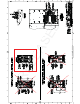
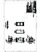
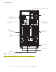
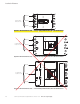
20. Terminals are UL and CSA rated at 75°C. See Table T for output power cable terminations. Paragraph A.5
shows the location of output power cable terminals inside of the PDU cabinet.
21. DO NOT overtighten the terminal lugs to prevent stripping the threads. Tighten lugs to the torque values
in Table T.
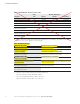
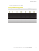
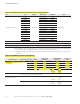
Table S. Recommended (or Equivalent) Installation Parts and Tools (Not Supplied by Eaton)
Part Size Quantity Manufacturer Part Number Notes
Long Barrel 2-Hole Lug
#8 AWG
As required
Thomas & Betts 54850BE
Copper wire only
#6 AWG Thomas & Betts 54852BE
#4 AWG Thomas & Betts 54854BE
#3 and #2 AWG Thomas & Betts 54856BE
#1 AWG Thomas & Betts 54858BE
1/0 AWG Thomas & Betts 54860BE
2/0 AWG Thomas & Betts 54862BE
3/0 AWG Thomas & Betts 54864BE
4/0 AWG Thomas & Betts 54866BE
250 MCM Thomas & Betts 54868BE
300 MCM Thomas & Betts 54870BE
350 MCM Thomas & Betts 54872BE
400 MCM Thomas & Betts 54874BE
500 MCM Thomas & Betts 54876BE
Manual Hydraulic Crimp Tool 14 Ton 1 Thomas & Betts TBM14M
Die Set N/A 1 Thomas & Betts 15506
NOTE Equivalent parts are acceptable.
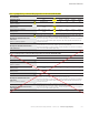
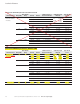
Table T. Eaton 150 kVA PDU Output Power Cable Terminations
Terminal Function Breaker Rating Terminal Function
Size of Pressure
Termination
Tightening Torque
Nm (lb in)
Type and Size
Screw
AC Output from Subfeed Breakers
to Critical Load
(“F” Frame) A Phase A 1 – 4/0 31 (275) 5/16” Hex
B Phase B 1 – 4/0 31 (275) 5/16” Hex
C Phase C 1 – 4/0 31 (275) 5/16” Hex
N Neutral 1 – 4/0 31 (275) 5/16” Hex
G Ground 84 – #4–#14 or 2 x #12–#14 #4–#6:
#8:
#10–#14:
4.0 (35)
2.8 (25)
2.3 (20)
Slotted
Wire branch circuits in accordance with branch circuit breaker manufacturer's ratings and instructions and national and local
electrical codes (output is prewired to the panelboard).
AC Output from Distribution Panel
Breakers to Critical Load
N/A N Neutral 84 – #4–#14 or 2 x #12–#14 #4–#6:
#8:
#10–#14:
4.0 (35)
2.8 (25)
2.3 (20)
Slotted
N/A G Ground 84 – #4–#14 or 2 x #12–#14 #4–#6:
#8:
#10–#14:
4.0 (35)
2.8 (25)
2.3 (20)
Slotted
Table S. Recommended
(
or E
q
uivalent
)
Install
a
t
ion Parts and Tools
(
Not Su
pp
lied by Eaton
)
Table T. Eaton 150 kVA PDU
O
utput Power
C
able Terminations
A
C
O
utput from
S
ubfeed Breakers
(“F” Frame)
A
Phase A
1 – 4/0
31 (275)
5/16” Hex
to
C
ritical Load
B
Phase B
1 – 4/0
31 (275)
5/16” Hex
C
Phase C
1 – 4/0
31 (275)
5/16” Hex
N
Neutral
1 – 4/0
31 (275)
5/16” Hex
G
Ground
84 – #4–#14 or 2 x #12–#14
#4–#6:
4
.0 (35)
#
8
:
2
.8 (25)
#1
0
–#14
:
2
.3
(
20
)