
Specifications


Installation Reference
A-56 Eaton PDU (150 kVA) Installation and Operation Manual 164202126—Rev 5 www.eaton.com/powerquality
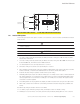
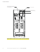
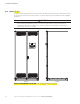
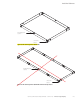
Figure A-46. PDU Interface Terminal Locations for Two PRL3 and Subfeed Breaker Monitoring
Terminals TB1 and TB2
(See Figure A-54 for details.)
X-Slot Communication Bay
UCB
Optional Aux and Shunt Trip Terminal Blocks
for PRL3 and Unmonitored Subfeed Breakers.
See Figure A-48 for details.
Figure A-46. PDU Inter
f
ace Terminal Locations for Two PRL3 and Subfeed Breaker Monitorin
g