
Installation guide

1027574 UPS 450-550 kVA (2x225 - 2x275 kVA) 55
Revision E User’s and Installation Guide
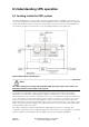
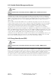
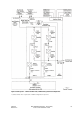
Figure 6-2. Path of current through the UPS in normal mode
During normal UPS operation, power for the system is derived from a utility input source through the
rectifier input contactor K1. The front panel displays Normal, indicating the incoming power is within
voltage and frequency acceptance windows. Three-phase AC input power is converted to DC using
IGBT devices to produce a regulated DC voltage to the inverter. The battery is charged directly from the
regulated rectifier output through a buck or boost DC converter, depending on the system voltage and
the size of the battery string attached to the unit.
The battery converter derives its input from the regulated DC output of the rectifier and provides
regulated charge current to the battery. The battery is always connected to the UPS and ready to
support the inverter should the utility input become unavailable.
The inverter produces a three-phase AC output to a customer’s load without the use of a transformer.
The inverter derives regulated DC from the rectifier and uses IGBT devices and pulse-width modulation
(PWM) to produce a regulated and filtered AC output. The AC output of the inverter is delivered to the
system output through the output contactor K3.
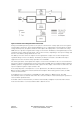
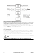
If the utility AC power is interrupted or is out of specification, the UPS automatically switches to
Battery mode to support the critical load without interruption. When utility power returns, the UPS
returns to Normal mode.
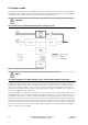
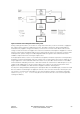
If the UPS becomes overloaded or unavailable, the UPS switches to Bypass mode. The UPS
automatically returns to Normal mode when the overload condition is cleared and system operation is
restored within specified limits.
If the UPS suffers an internal failure, it switches automatically to Bypass mode and remains in that
mode until the failure is corrected and the UPS is back in service.