
Installation guide

70 UPS 450-550 kVA (2x225 - 2x275 kVA) 1027574
User’s and Installation Guide Revision E
6.5 Multiple UPS distributed bypass system oneline
configurations
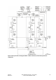
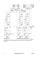
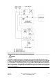
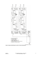
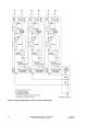
The distributed bypass system oneline drawings in this section show the simplified internal structure of
the UPS, battery supply, and basic maintenance bypass in a multiple UPS configuration. These onelines
do not show each UPM in the UPSs, but represent each UPS in the distributed bypass system. The
internal structure of each UPS is shown in Figure 6-6 through Figure 6-9 starting on page 61.
NOTE
If the load requires a neutral, a bypass source neutral must be provided. If the load does not
require a neutral and there is no neutral conductor connected at the bypass input, a UPS neutral
must be connected to source star point.
Oneline Drawing UPS Model
Voltage
System Type
Input Output
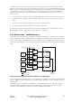
Figure 6-14 on page 71 9395-450
9395-550
400 400 Multiple UPS - Distributed Bypass 1+1 and 2+0
Configurations
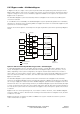
Figure 6-15 on page 72 9395-450
9395-550
400 400 Multiple UPS - Distributed Bypass 2+1 and 3+0
Configurations
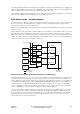
Figure 6-16 on page 73 9395-450
9395-550
400 400 Multiple UPS - Distributed Bypass 3+1 and 4+0
Configurations