
Operating instructions


UNDERSTANDING UPS OPERATION
EATON Eaton 9395 550/275 UPS (225–550 kVA) Installation and Operation Manual S 164201716 Rev 2 www.eaton.com/powerquality
6-18
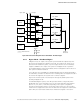
If at any time during the battery discharge the input power becomes available again,
the rectifier begins to supply DC current to the inverter. At this point, the UPS returns
to Online mode. If at any time during the battery discharge the AC input power
becomes available again, each rectifier turns on, assumes the inverter load from the
batteries, and begins recharging the batteries. Depending on the total load and the
duration of the battery discharge, battery and rectifier input current limit alarms may
be seen for a short time due to the current required to recharge the batteries.
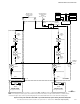
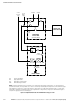
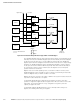
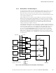
6.5 Multiple UPS Distributed Bypass System Oneline Configurations
The distributed bypass system oneline drawings in this section show the simplified
internal structure of the UPS, battery supply, and basic maintenance bypass in a
multiple UPS configuration. These onelines do not show each UPM in the UPSs, but
represent each UPS in the distributed bypass system. The internal structure of each
UPS is shown in Figure 6‐5 through Figure 6‐8 starting on page 6-8.
Oneline Drawing UPS Model
Voltage
System Type
Input Output
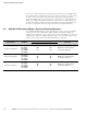
Figure 6‐13 on page 6-19
9395-550/225
9395-550/275
9395-550/450
9395-550/500
9395-550/550
400
480
400
480
Multiple UPS – Distributed Bypass
1+1 and 2+0 Configurations
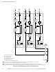
Figure 6‐14 on page 6-20
9395-550/225
9395-550/275
9395-550/450
9395-550/500
9395-550/550
400
480
400
480
Multiple UPS – Distributed Bypass
2+1 and 3+0 Configurations
Figure 6‐15 on page 6-21
9395-550/225
9395-550/275
9395-550/450
9395-550/500
9395-550/550
400
480
400
480
Multiple UPS – Distributed Bypass
3+1 and 4+0 Configurations