
Installation Manual


7
Instruction Leafl et IL03303001E
Effective February 2009
Instructions for A200, A210, A250 size 6, two- or three-pole
non-reversing or reversing motor controllers
EATON CORPORATION www.eaton.com
Magnet suspension
Both the stationary and moving magnet assemblies are flexibly
mounted to ensure proper sealing of the magnet for quiet operation.
Both helical compression springs and flat leaf springs are in back of
each magnet part. The moving armature has less spring force and
restraint than the stiffer stationary magnet assembly. In case these
magnets are ever disassembled, particular care must be used to
make sure that the flat leaf springs are centered on the laminated
magnet assemblies and are not jammed between the magnets and
the molded guide projections. After reassembly, be sure to check
that both the stationary and moving magnets can be manually
depressed or rocked in their mountings. Again, the moving armature
assembly can be rocked with much less force and more freedom
than the stationary assembly.
Contact overtravel and replacement
The initial contact overtravel, with new contacts, is 5/32 to 13/64
inches and is measured with the power off as shown in Figures 5
and 6. Contact replacement is necessary when the overtravel on any
pole has been reduced to 3/64 inch. The contacts must be replaced
on all poles at the same time. Contact replacement is then achieved
by the following procedure with the power off:
1. Remove the arc box and gently lower the crossbar.
2. Disconnect shunts from moving contact.
3. Remove the three contact springs and their protectors.
Remove the nameplate.
4. Remove the moving contacts by removing their bearing pins.
(A 5/3-inch allen wrench is required for the #10 socket head
cap screws.)
5. Remove the stationary contacts. (A 1/4-inch allen wrench is
required for the 5/16-inch socket head cap screws.)
To install new contacts, reverse the procedure, making sure all bolts
and screws are tight (the stationary contact mounting bolts must be
tightened to 150–175 pound inches), the crossbar is raised into its
proper position with the moving contacts inside the arc box, and
the arc box is securely in place. Check to be sure both kickout and
contact springs are properly seated and the nameplate is in place.
The moving contacts should touch the stationary contacts at the
same instant within 1/16 inch maximum error on all poles as the
contactor is closed. Contact face misalignment of approximately
1/16 inch (measured with the contactor fully closed) will not be
detrimental to the operation of the contactor.
Contact forces
With new contacts, the total contact forces per pole should be:
•
Initial force 7.5 to 8.5 pounds (Figure 5)
•
Final force 9 to 10 pounds (Figure 6)
After turning off the power, contact forces per pole may be
measured by exerting a measured pull until the paper is allowed
to move using the method shown in Figures 5 and 6.
Arc box
The arc box provides the mechanical stop for the moving contact
assembly while maintaining the proper open gap for the main
contacts. The molded box also supports the De-ionT type arc
quenchers that are contained within the arc box. Two front
accessible bolts hold the arc box in place. This arc box requires
no maintenance except for a periodic inspection for grid damage
or zircon liner burn-through by fault conditions. The contactor must
never be operated in a power circuit unless the arc box is securely
bolted in place.
Kickout springs
Normally no maintenance is required for these springs other than to
make sure they are properly seated on the molded crossbar assem-
bly. In case they are inadvertently removed from the molded base
where they are captivated in a hole slightly smaller than the free
spring outside diameter, they can be reinstalled readily with
needlenose pliers. Hold the front end of the spring, insert the
pliers inside the spring, and rotate the offset pin end of the spring
in a direction to decrease its outside diameter. Keep the spring
restrained until the pin end has been inserted into the molded base.
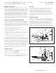
Figure 5. Initial contact force and spring length measurement
Figure 6. Final contact force and spring length measurement
Spring
Scale
String
or Wire
Initial
Length
Moving
Contact
Stationary
Contact
Mounting
Surface
Pull
Scale
Armature Open
Thin Paper Feeler Folded
Under Moving Contact
Thin Paper
Feeler
Stationary
Contact
Moving
Contact
Final
Length
Pull
Contact Spring
“Power Off” Armature Held
Fully Closed Manually
Contact
Overtravel
=
Initial
Length
Final
Length