
Install Instructions

Instruction Leafl et IL17055
Effective March 2015
Supersedes June 1998
Contents
Description . . . . . . . . . . . . . . . . . . . . . . . . . . . . . . . . Page
The Controller . . . . . . . . . . . . . . . . . . . . . . . . . . . . . . . . . 1
Installation . . . . . . . . . . . . . . . . . . . . . . . . . . . . . . . . . . . . 2
Type B Overload Relay. . . . . . . . . . . . . . . . . . . . . . . . . . . 3
Type A Overload Relay . . . . . . . . . . . . . . . . . . . . . . . . . . . 3
Overload Relay Heaters . . . . . . . . . . . . . . . . . . . . . . . . . . 3
Type GCO Current Transformers . . . . . . . . . . . . . . . . . . . 4
Coverage . . . . . . . . . . . . . . . . . . . . . . . . . . . . . . . . . . . . . 4
Control Relay . . . . . . . . . . . . . . . . . . . . . . . . . . . . . . . . . . 5
Auxiliary Contacts—Type J . . . . . . . . . . . . . . . . . . . . . . . 6
Line And Load Terminals . . . . . . . . . . . . . . . . . . . . . . . . . 6
Mechanical Interlocks . . . . . . . . . . . . . . . . . . . . . . . . . . . 6
Maintenance . . . . . . . . . . . . . . . . . . . . . . . . . . . . . . . . . . 7
Magnet Suspension . . . . . . . . . . . . . . . . . . . . . . . . . . . . 7
Contact Overtravel And Replacement . . . . . . . . . . . . . . . 7
Contact Forces . . . . . . . . . . . . . . . . . . . . . . . . . . . . . . . . 7
Arc Box . . . . . . . . . . . . . . . . . . . . . . . . . . . . . . . . . . . . . . 7
Kickout Springs . . . . . . . . . . . . . . . . . . . . . . . . . . . . . . . . 8
Operating Coil . . . . . . . . . . . . . . . . . . . . . . . . . . . . . . . . . 8
AC/DC Coils . . . . . . . . . . . . . . . . . . . . . . . . . . . . . . . . . . . 8
Renewal Parts . . . . . . . . . . . . . . . . . . . . . . . . . . . . . . . . . 9
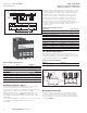
The Controller
An A200, A210, or A250 motor controller, when wired as
shown in the appropriate connection diagram, will oper-
ate as a full-voltage starter and will give protection against
overload, but not against short-circuit currents when wired
and provided with overload relay (OLR) heaters as listed in
heater selection tables or when used with any means of
inherent protection activated by motor temperature.
This industrial type-controller is designed to be installed,
operated, and maintained by adequately trained workmen.
These instructions do not cover all details, variations, or
combinations of the equipment, its storage, delivery, instal-
lation, checkout, safe operation, or maintenance. Care
must be exercised to comply with local, state, and national
regulations, as well as safety practices, for this class of
equipment.
This motor controller is suitable for use on a circuit capable
of delivering not more than the current (rms symmetrical
amperes) shown in Table 1 in circuits rated not more than
the voltage shown.
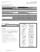
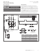
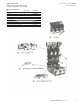
A200, A210, A250
Size 6, 2-3 Pole Non-Reversing
or Reversing Motor Controllers
Figure 1. Size 6 A200 Non-reversing Controller