Electrical Sector Solutions Volume 1: Residential and Light Commercial
Volume 1—Residential and Light Commercial Tab 1—Loadcenters and Circuit Breakers . . . . . . . . . . . . . . . . . . . . . . V1-T1-1 Tab 2—Surge Protection . . . . . . . . . . . . . . . . . . . . . . . . . . . . . . . . . . . . V1-T2-1 Tab 3—Residential Standby Backup Power Solutions . . . . . . . . . . . . V1-T3-1 Tab 4—Metering Products . . . . . . . . . . . . . . . . . . . . . . . . . . . . . . . . . . V1-T4-1 Tab 5—Power Pedestals . . . . . . . . . . . . . . . . . . . . . . . . . . . . . . . . .
Copyright Dimensions, Weights and Ratings Dimensions, weights and ratings given in this catalog are approximate and should not be used for construction purposes. Drawings containing exact dimensions are available upon request. All listed product specifications and ratings are subject to change without notice. Photographs are representative of production units. Terms and Conditions All prices and discounts are subject to change without notice.
Introduction Eaton is a global leader in power distribution, power quality, control and automation, and monitoring products. At Eaton, we believe a reliable, efficient and safe power system is the foundation of every successful enterprise. Through innovative technologies, cutting-edge products and our highly skilled services team, we empower businesses around the world to achieve a powerful advantage.
Introduction Icons Green Leaf Eaton Green Solutions are products, systems or solutions that represent Eaton benchmarks for environmental performance. The green leaf symbol is our promise that the solution has been reviewed and documented as offering exceptional, industry-leading environmental benefits to customers, consumers and our communities.
Loadcenters and Circuit Breakers Residential Loadcenters and Breaker Family 1.1 Type CH Loadcenters and Circuit Breakers Overview . . . . . . . . . . . . . . . . . . . . . . . . . . . . . . . . . . . . . . . . . . . . . . . Single-Phase . . . . . . . . . . . . . . . . . . . . . . . . . . . . . . . . . . . . . . . . . . Three-Phase . . . . . . . . . . . . . . . . . . . . . . . . . . . . . . . . . . . . . . . . . . . CH Specialty Products . . . . . . . . . . . . . . . . . . . . . . . . . . . . . . . . . . .
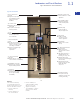
1.1 1 Loadcenters and Circuit Breakers Type CH Loadcenters and Circuit Breakers Eaton Type CH Convertible Family Contents Description 1 Overview Product Description . . . . . . . . . . . . . . . . . . . . . Features, Benefits and Functions . . . . . . . . . . Standards and Certifications . . . . . . . . . . . . . . Catalog Number Selection . . . . . . . . . . . . . . . . Product Selection. . . . . . . . . . . . . . . . . . . . . . . Technical Data and Specifications . . . . . . . . . .
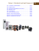
Loadcenters and Circuit Breakers Type CH Loadcenters and Circuit Breakers Product Description Features, Benefits and Functions Loadcenters are enclosures specifically designed to house the branch circuit breakers and wiring required to distribute power to individual circuits. They contain either a main breaker when used at the service entrance point or a main lug when used as a sub-panel to add circuits to existing service.
1.1 Loadcenters and Circuit Breakers Type CH Loadcenters and Circuit Breakers 1 Standards and Certifications 1 UL® Listings All Eaton Type CH loadcenters are listed under UL File E8741. 1 1 1 1 1 1 1 1 1 1 1 1 1 1 1 1 1 1 Neutral and Ground Terminals The standard terminals on grounds and neutrals are rated to accept (3)—#14–#10 Cu/Al or (1)—#14–4 wires. For larger cables, add-on neutral lugs may be ordered from the Accessories.
Loadcenters and Circuit Breakers Type CH Loadcenters and Circuit Breakers 1.1 Type CH Loadcenter 1 Extra 1.5 inch Knockout (38.
1.1 Loadcenters and Circuit Breakers Type CH Loadcenters and Circuit Breakers 1 Catalog Number Selection 1 Loadcenters 100–225 A and 12–42 Circuits CH 42 B 1 1 LC Type Type CH 3/4-inch (19.
1.1 Loadcenters and Circuit Breakers Type CH Loadcenters and Circuit Breakers Product Selection 1 Single-Phase—Main Circuit Breaker Loadcenters—10/25 kAIC CH42B200K 1 Single-Phase Three-Wire—120/240 Vac—Insulated/Bondable Split Neutral (Unless Otherwise Noted) Main Breaker Type Main Ampere Rating Maximum Number 3/4-Inch (19.
1.1 Loadcenters and Circuit Breakers Type CH Loadcenters and Circuit Breakers 1 Single-Phase—High Interrupting Rated Main Circuit Breaker Loadcenters—100 kAIC 1 Single-Phase Three-Wire—120/240 Vac—Insulated/Bondable Split Neutral 1 Main Breaker Type Main Ampere Rating Maximum Number 3/4-Inch (19.
Loadcenters and Circuit Breakers Type CH Loadcenters and Circuit Breakers 1.1 Single-Phase—Main Lug Loadcenters 1 1 Single-Phase Three-Wire—120/240 Vac—Insulated/Bondable Single Neutral Surface Outdoor Main Ampere Rating Maximum Number 3/4-Inch (19.
1.1 1 CH42L225G 1 1 Loadcenters and Circuit Breakers Type CH Loadcenters and Circuit Breakers Single-Phase Three-Wire—120/240 Vac—Insulated/Bondable Split Neutral—Factory-Installed Ground Bar Loadcenter Cover Catalog Number Main Ampere Rating Maximum Number 3/4-Inch (19.
1.1 Loadcenters and Circuit Breakers Type CH Loadcenters and Circuit Breakers Convertible Loadcenters MCB or MLO—Base Units and Main Devices—10/25/35 kAIC Complete assembly consists of: loadcenter, cover, and either main breaker kit or main lug kit.
1.1 Loadcenters and Circuit Breakers Type CH Loadcenters and Circuit Breakers 1 Three-Phase—Main Circuit Breaker Loadcenters—10 kAIC 1 CH42B3200L Three-Phase Four-Wire—208Y/120 Vac or 240 Vac Insulated/Bondable Split Neutral 1 1 Main Ampere Rating Maximum Number 3/4-Inch (19.
1.1 Loadcenters and Circuit Breakers Type CH Loadcenters and Circuit Breakers Three-Phase—Main Lug Loadcenters 1 Three-Phase Four-Wire—208Y/120 Vac or 240 Vac Insulated/Bondable Split Neutral (Unless Otherwise Noted) Main Ampere Rating Maximum Number 3/4-Inch (19.
1.1 1 Loadcenters and Circuit Breakers Type CH Loadcenters and Circuit Breakers Contents—CH Specialty Products Spa Panels Description 1 Page Overview . . . . . . . . . . . . . . . . . . . . . . . . . . . . . . . . CH Specialty Products Spa Panels Surge Panel . . . . . . . . . . . . . . . . . . . . . . . . . . . . Plug-On Neutral Loadcenter . . . . . . . . . . . . . . . Type CH Renovation Loadcenter . . . . . . . . . . . . Type CH Retrofit Interior Kits . . . . . . . . . . . . . .
Loadcenters and Circuit Breakers Type CH Loadcenters and Circuit Breakers 1.1 Contents—CH Specialty Products Surge Panel Description Page Overview . . . . . . . . . . . . . . . . . . . . . . . . . . . . . . . CH Specialty Products Spa Panels . . . . . . . . . . . . . . . . . . . . . . . . . . . . Surge Panel Plug-On Neutral Loadcenter . . . . . . . . . . . . . . Type CH Renovation Loadcenter . . . . . . . . . . . Type CH Retrofit Interior Kits . . . . . . . . . . . . . .
1.
1.1 Loadcenters and Circuit Breakers Type CH Loadcenters and Circuit Breakers Contents—CH Specialty Products 60-Circuit Plug-On Neutral Loadcenter Description Page Overview . . . . . . . . . . . . . . . . . . . . . . . . . . . . . . . CH Specialty Products Spa Panels . . . . . . . . . . . . . . . . . . . . . . . . . . . . Surge Panel . . . . . . . . . . . . . . . . . . . . . . . . . . . Plug-On Neutral Loadcenter Type CH Renovation Loadcenter . . . . . . . . . . . Type CH Retrofit Interior Kits . . .
1.1 1 Loadcenters and Circuit Breakers Type CH Loadcenters and Circuit Breakers Contents—CH Specialty Products Renovation Panel Description 1 Page Overview . . . . . . . . . . . . . . . . . . . . . . . . . . . . . . . . CH Specialty Products Spa Panels. . . . . . . . . . . . . . . . . . . . . . . . . . . . . Surge Panel . . . . . . . . . . . . . . . . . . . . . . . . . . . . Plug-On Neutral Loadcenter . . . . . . . . . . . . . . . Type CH Renovation Loadcenter Type CH Retrofit Interior Kits . . . . .
Loadcenters and Circuit Breakers Type CH Loadcenters and Circuit Breakers 1.1 Contents—CH Specialty Products Type CH Retrofit Interior Description Page Overview . . . . . . . . . . . . . . . . . . . . . . . . . . . . . . . CH Specialty Products Spa Panels . . . . . . . . . . . . . . . . . . . . . . . . . . . . Surge Panel . . . . . . . . . . . . . . . . . . . . . . . . . . . Plug-On Neutral Loadcenter . . . . . . . . . . . . . . Type CH Renovation Loadcenter . . . . . . . . . . .
1.1 1 1 1 1 1 1 1 1 1 1 1 1 1 Loadcenters and Circuit Breakers Type CH Loadcenters and Circuit Breakers CH Specialty Product Selection To select the retrofit kit: 1. From the existing box size determine which retrofit groups are suitable (may be more than one). 2. Use type of interior, number of phases, and type of main to find the selection chart. 3. Select part number from chart (if main breaker, replace XXX with specific amp rating). 4.
Loadcenters and Circuit Breakers Type CH Loadcenters and Circuit Breakers 1.1 Complete Assembly Note: For complete assembly, interior and cover need to be ordered separately.
1.1 1 1 Loadcenters and Circuit Breakers Type CH Loadcenters and Circuit Breakers CH Loadcenter Options and Accessories CHSF2125 Field Installation and Parts 1 Description Ordering Quantity 1 Catalog Number Sub-feed lug blocks—two-pole, 125 A, 3/4-inch (19.1 mm) spaces needed 1 CHSF2125 1 Sub-feed lug blocks—three-pole, 125 A, 3/4-inch (19.1 mm) spaces needed 1 CHSF3125 Neutral/ground lug—add-on neutral or ground lug 1 NL20 1 NL30 1 NL300 1 Filler plates—3/4-inch (19.
Loadcenters and Circuit Breakers Type CH Loadcenters and Circuit Breakers 1.1 Mechanical Interlock Covers Covers mechanically interlock two breakers. Type A covers interlock two CH breakers mounted across from one another. Type B covers interlock a main Type CSR breaker with a Type CH.
1.
Loadcenters and Circuit Breakers Type CH Loadcenters and Circuit Breakers DS100H1 1.1 Field Installation Rainproof Conduit Hubs Conduit Size Catalog Number Description Inches (mm) Ordering Quantity 1 Group 1—for use with 70, 100 and 125 A MLO and MCB loadcenters and circuit breaker enclosures 0.75 (19.1) 1 DS075H1 1.00 (25.4) 1 DS100H1 1.25 (31.8) 1 DS125H1 1.50 (38.1) 1 DS150H1 2.00 (50.8) 1 DS200H1 2.00 (50.8) 1 DS200H2 2.50 (63.5) 1 DS250H2 3.00 (76.
1.1 1 1 Loadcenters and Circuit Breakers Type CH Loadcenters and Circuit Breakers Decorator Cover Accessory ● For easy use with CH loadcenters mounted in living space ● Easily wallpapered or painted to match any decor ● Loadcenter accessory—exclusively from Eaton 1 1 Loadcenter Goof Collars Don’t let an ugly drywall problem ruin a beautiful electrical installation. Eaton’s Goof Collar is designed to cover gaps between the finished drywall and loadcenter enclosure.
1.1 Loadcenters and Circuit Breakers Type CH Loadcenters and Circuit Breakers Dimensions 1 Approximate Dimensions in Inches (mm) 1 Residential Loadcenter Knockout Residential NEMA Type 1 Indoor and NEMA Type 3R Outdoor Enclosures. Residential/Commercial/Unit Enclosure—Box Sizes Note: Box sizes do not include covers/fronts. 1 Residential Loadcenters Box Size Height Width Depth 1 Knockouts for Box Sizes 5, 6, 7, 5R, 6R, 7R Code Diameter 5 9.50 (241.3) 4.50 (114.3) 3.13 (79.4) A 0.50 (12.
1.1 1 1 1 1 Loadcenters and Circuit Breakers Type CH Loadcenters and Circuit Breakers Approximate Dimensions in Inches (mm) Residential and Commercial Loadcenter Knockout Residential NEMA Type 1 indoor and NEMA Type 3R outdoor enclosures. Knockouts for Box Sizes 8, 8R, P, PM, B, C, D, E, G, J, K, L, N and Outdoor Boxes 12–60 Circuits Type ECB and ECC Unit Enclosure Knockout Code Diameter Code Diameter a 0.75 (19.1) — — — — b 0.50 (12.7) 0.75 (19.1) — — — 1 c 0.50 (12.
Loadcenters and Circuit Breakers Type CH Loadcenters and Circuit Breakers 1.1 Technical Data and Specifications General A. The Contractor shall furnish and install loadcenters incorporating circuit breakers of the number, rating and type as specified herein and as shown on the contract drawings. Ratings A. Loadcenters shall be rated for 240 Vac and shall have short-circuit ratings as shown on the drawings or as herein scheduled, but not less than 10,000 amperes rms symmetrical. B.
1.1 1 1 1 1 1 1 1 1 1 1 1 1 1 1 1 1 1 1 Loadcenters and Circuit Breakers Type CH Loadcenters and Circuit Breakers Enclosures A. Loadcenters shall have NEMA 1 general purpose or NEMA 3R rainproof enclosures as indicated on the drawings and shall be surface or flush mounted except where noted. B. For indoor applications, enclosures shall be rated NEMA 1. Enclosures shall be manufactured from cold-rolled codegauge sheet steel having multiple knockouts and painted per paint specification.
Loadcenters and Circuit Breakers Type CH Loadcenters and Circuit Breakers 1.1 Contents Plug-On Circuit Breakers Description Overview . . . . . . . . . . . . . . . . . . . . . . . . . . . . . . . CH Specialty Products . . . . . . . . . . . . . . . . . . . . . CH Loadcenter Options and Accessories . . . . . . . CH Circuit Breakers Product Selection. . . . . . . . . . . . . . . . . . . . . . . Options and Accessories . . . . . . . . . . . . . . . . . Technical Data and Specifications . . . . . . . . . .
1.1 Loadcenters and Circuit Breakers Type CH Loadcenters and Circuit Breakers 1 Product Selection 1 10 kAIC, 120 Vac, 120/240 Vac and 240 Vac 1 Type CH Plug-On Circuit Breakers Type CH Breakers, 3/4-Inch (19.1 mm) per Pole 120, 120/240 or 240 Vac, 10 kAIC Catalog Number 1 1 Ampere Rating 1 10 1 15 (1) #14–8 1 (2) #14–10 12 (1) #14–6 3 25 30 1 1 Two-Pole 120/240 Vac Common Trip Requires Two 3/4-Inch (19.
1.1 Loadcenters and Circuit Breakers Type CH Loadcenters and Circuit Breakers Type CH AF/GF Single-Pole Circuit Breaker Type CH AFCI SinglePole Circuit Breaker Poles Single-pole 10 kAIC Single-pole, plug-on neutral 10 kAIC Type CH AFCI SinglePole Circuit Breaker 1 Dual Purpose Arc Fault/Ground Fault 3/4-Inch (19.
1.1 Loadcenters and Circuit Breakers Type CH Loadcenters and Circuit Breakers 1 Plug-On Ground Fault Circuit Breakers, Type CH 10 kAIC, 120 Vac and 120/240 Vac 1 Type CH Single-Pole Type CH Ground Fault Circuit Breakers (5 Milliampere) 3/4-Inch (19.1 mm) per Pole 120 Vac or 120/240 Vac,10 kAIC Catalog Number—1 per Shelf Carton 1 1 Single-Pole 120 Vac Requires One 3/4-Inch (19.1 mm) Space Two-Pole 120/240 Vac Common Trip Requires Two 3/4-Inch (19.
Loadcenters and Circuit Breakers Type CH Loadcenters and Circuit Breakers 1.1 Type CH-HID Circuit Breakers—10 kAIC, 120 Vac, 120/240 and 240 Vac Suitable for use in circuits for fluorescent and high intensity discharge lighting. Also suitable for HACR applications. 1 1 3/4-Inch (19.1 mm) per Pole 120 Vac, 120/240 and 240 Vac, 10 kAIC Ampere Rating Single-Pole 120/240 Vac Requires One 3/4-Inch (19.1 mm) Space Two-Pole 240 Vac Common Trip Requires Two 3/4-Inch (19.
1.1 1 1 Loadcenters and Circuit Breakers Type CH Loadcenters and Circuit Breakers Type CHP Commercial Breakers—10 kAIC, 120 Vac, 120/240 Vac and 240 Vac Note: CHP breakers feature on-off and trip positions for commercial applications. 3/4-Inch (19.1 mm) per Pole 120, 120/240 or 240 Vac, 10 kAIC 1 1 1 1 1 1 1 1 Ampere Rating Wire Size Range Cu/Al 60 °C or 75 °C 10 (1) #14–8 1 (2) #14–10 12 (1) #14–6 3 Single-Pole 120/240 Vac Requires One 3/4-Inch (19.
Loadcenters and Circuit Breakers Type CH Loadcenters and Circuit Breakers 1.1 Type CHP Neutral Switching Breakers—10 kAIC, 120 Vac and 120/240 Vac Used to open the neutral along power line(s) for applications of gas pumps. 1 1 3/4-Inch (19.1 mm) per Pole 120 or 120/240 Vac, 10 kAIC Two-Pole 120 Vac Common Trip Requires Two 3/4-Inch (19.1 mm) Spaces Three-Pole 120/240 Vac Common Trip Requires Three 3/4-Inch (19.
1.1 1 1 CHHT Field Installation Kits and Parts Description 1 Handle tie bar for physically joining the handles of two adjacent single-pole Type CH circuit breakers (molded plastic handle cover) CHPL CHHT CHPLGF Padlockable device for locking the handle of single-, two- or three-pole Type CH circuit breakers (escutcheon mounted) 5 1 CHPL 1 CHPLGF Padlockable device for locking the handle of main circuit breaker Types CC and CCH into the ON or OFF position.
Loadcenters and Circuit Breakers Type CH Loadcenters and Circuit Breakers 1.1 Shunt Trip Options Description Type Volts Catalog Number Suffix Adder 1 CSR 12 DC SR12 CSR 24 DC SR24 CSR 120 AC SR01 CH 120 AC ST 2 CC 12 DC SR12 CC 24 DC SR24 CC 120 AC SR01 CC 208 AC SR08 CC 240 AC SR02 1 1 1 1 1 1 1 1 Handle Position Changeability Chart 1 To Change Handle Position from ON to OFF or OFF to ON You Must...
1.1 Loadcenters and Circuit Breakers Type CH Loadcenters and Circuit Breakers 1 Technical Data and Specifications 1 Ratings Single- and two-pole CH breakers rated 15 and 20 A have low instantaneous magnetic trip levels. The 15 and 20 A breakers with “HM” suffix have high magnetic trip settings recommended for circuits with inherently high inrush currents. All Type CH breakers are marked for heating, air conditioning and refrigeration (HACR) equipment application.
Loadcenters and Circuit Breakers Type CH Loadcenters and Circuit Breakers 1.
1.2 1 Loadcenters and Circuit Breakers Type BR Loadcenters and Circuit Breakers Type BR Loadcenters and Circuit Breakers Contents Description 1 Overview Product Description . . . . . . . . . . . . . . . . . . . . . Features, Benefits and Functions . . . . . . . . . . Standards and Certifications . . . . . . . . . . . . . . Catalog Number Selection . . . . . . . . . . . . . . . . Product Selection. . . . . . . . . . . . . . . . . . . . . . . BR Specialty Products BR Quick Connect Neutral Loadcenters . .
Loadcenters and Circuit Breakers Type BR Loadcenters and Circuit Breakers 1.2 Product Description Loadcenters are enclosures specifically designed to house the branch circuit breakers and wiring required to distribute power to individual circuits. They contain either a main breaker when used at the service entrance point or a main lug when used as a sub-panel to add circuits to existing service. The main breaker protects the main entire panel and can be used as a service disconnect.
1.2 1 1 1 Loadcenters and Circuit Breakers Type BR Loadcenters and Circuit Breakers Type BR Loadcenter Extra 1.5 inch Knockout (38.
1.2 Loadcenters and Circuit Breakers Type BR Loadcenters and Circuit Breakers Standards and Certifications Catalog Number Selection UL Listings All Eaton Type BR loadcenters are listed under UL File E52977 except the 2–8 circuit loadcenters, up through and including 125 A, which are listed under UL File E8741.
1.2 1 1 Loadcenters and Circuit Breakers Type BR Loadcenters and Circuit Breakers Product Selection Single-Phase—Main Circuit Breaker Loadcenters—10/25 kAIC Single-Phase Three-Wire—120/240 Vac—Insulated/Bondable Split Neutral BR4040B200 Main Breaker Type Main Ampere Rating Maximum Number 1-Inch (25.
1.2 Loadcenters and Circuit Breakers Type BR Loadcenters and Circuit Breakers Main Circuit Breaker Loadcenters—10/22 kAIC B4242DFN 1 Single-Phase Three-Wire—120/240 Vac—Insulated/Bondable Split Neutral Main Breaker Type Main Ampere Rating DK 4 HLD 6 Maximum Number 1-Inch (25.
1.
1.2 Loadcenters and Circuit Breakers Type BR Loadcenters and Circuit Breakers Single-Phase—Main Lug Loadcenters 1 Single-Phase Three-Wire—120/240 Vac—Insulated/Bondable Split Neutral, continued Main Ampere Rating BR1224L125 125 150 BR1224L200 200 225 Maximum Number 1-Inch (25.
1.2 Loadcenters and Circuit Breakers Type BR Loadcenters and Circuit Breakers 1 Single-Phase—Main Lug Loadcenters—400 and 600 A 1 4242DFN Single-Phase Three-Wire—120/240 Vac—Insulated/Bondable Split Neutral Maximum Number 1-Inch (25.
1.2 Loadcenters and Circuit Breakers Type BR Loadcenters and Circuit Breakers Convertible Loadcenters MCB or MLO—Base Units and Main Devices 10/22/25 kAIC, Complete Assembly Consists of: Loadcenter and Either Main Breaker Kit or Main Lug Kit 1 Note: Interrupting rating depends on main circuit breaker selected. 1 BR3040N200 1 Base Units—Single-Phase Three-Wire—120/240 Vac—Insulated/Bondable Split Neutral (Unless Otherwise Noted) Main Ampere Rating 1 125 4 200 8 Maximum Number 1-Inch (25.
1.2 Loadcenters and Circuit Breakers Type BR Loadcenters and Circuit Breakers 1 Convertible Loadcenters MCB or MLO—Base Units and Main Devices 10/22/25 kAIC, Complete Assembly Consists of: Loadcenter and Either Main Breaker Kit or Main Lug Kit 1 Note: Interrupting rating depends on main circuit breaker selected.
1.2 Loadcenters and Circuit Breakers Type BR Loadcenters and Circuit Breakers Convertible Loadcenters—Copper Bus 10/22/25 kAIC BR3040NC200 1 Convertible—Single-Phase, Three-Wire—120/240 Vac—Insulated/Bondable Split Neutral Main Ampere Rating 125 10/22 kAIC 45 200 10/25 kAIC 49 Maximum Number 1-Inch (25.
1.2 1 Loadcenters and Circuit Breakers Type BR Loadcenters and Circuit Breakers Three-Phase—Type BR Main Circuit Breaker Loadcenters Three-Phase, Four-Wire—Main Lug Loadcenters—Copper Bus—208Y/120 Vac or 240 Vac, Insulated/Bondable Split Neutral 1 1 Main Ampere Rating 125 125 150 150 200 200 200 200 200 200 225 225 400 1 1 1 1 1 1 1 600 Maximum Number 1-Inch (25.
Loadcenters and Circuit Breakers Type BR Loadcenters and Circuit Breakers 3BR1224L125 Three-Phase, Four-Wire—Main Lug Loadcenters—Aluminum Bus—208Y/120 Vac or 240 Vac, Insulated/Bondable (Unless Otherwise Noted) Main Ampere Rating 100 125 150 200 225 3BR4242L400F 1.2 Maximum Number 1-Inch (25.
1.2 1 3BR3030N100 1 1 Loadcenters and Circuit Breakers Type BR Loadcenters and Circuit Breakers Three-Phase, Four-Wire—Convertible Loadcenters—Aluminum Bus—208Y/120 Vac or 240 Vac, Insulated/Bondable Split Neutral Spaces 100 4 30 3BR4242N225NY 1 1 Wire Size Range Cu/Al 60 °C or 75 °C for Main Loadcenter Catalog Number 23 (With Combination or NEMA Type 3R Cover) See main breaker and main lug kit tables below.
Loadcenters and Circuit Breakers Type BR Loadcenters and Circuit Breakers 1.2 Contents—BR Specialty Products BR Quick Connect Neutral Loadcenters Description Page Overview . . . . . . . . . . . . . . . . . . . . . . . . . . . . . . . BR Specialty Products BR Quick Connect Neutral Loadcenters Spa Panels . . . . . . . . . . . . . . . . . . . . . . . . . . . . Riser Panel. . . . . . . . . . . . . . . . . . . . . . . . . . . . Type BR Renovation Loadcenter . . . . . . . . . . .
1.2 1 Loadcenters and Circuit Breakers Type BR Loadcenters and Circuit Breakers Contents—BR Specialty Products Spa Panels Description 1 Page Overview . . . . . . . . . . . . . . . . . . . . . . . . . . . . . . . . BR Specialty Products BR Quick Connect Neutral Loadcenters . . . . . . Spa Panels Riser Panel . . . . . . . . . . . . . . . . . . . . . . . . . . . . Type BR Renovation Loadcenter . . . . . . . . . . . . Type BR Mechanical Interlock Kits . . . . . . . . . . Type BR Retrofit Interior Kits. .
1.2 Loadcenters and Circuit Breakers Type BR Loadcenters and Circuit Breakers Contents—BR Specialty Products Riser Panel Description Page Overview . . . . . . . . . . . . . . . . . . . . . . . . . . . . . . . BR Specialty Products BR Quick Connect Neutral Loadcenters . . . . . Spa Panels . . . . . . . . . . . . . . . . . . . . . . . . . . . . Riser Panel Type BR Renovation Loadcenter . . . . . . . . . . . Type BR Retrofit Interior Kits . . . . . . . . . . . . . . BR Circuit Breakers. . . . . . . . . .
1.2 1 Loadcenters and Circuit Breakers Type BR Loadcenters and Circuit Breakers Contents—BR Specialty Products BR Renovation Loadcenters Description 1 Page Overview . . . . . . . . . . . . . . . . . . . . . . . . . . . . . . . BR Specialty Products BR Quick Connect Neutral Loadcenters . . . . . Spa Panels . . . . . . . . . . . . . . . . . . . . . . . . . . . . Riser Panel. . . . . . . . . . . . . . . . . . . . . . . . . . . . Type BR Renovation Loadcenter Options and Accessories . . . . . . . . . . .
1.2 Loadcenters and Circuit Breakers Type BR Loadcenters and Circuit Breakers Options and Accessories BRSF125 1 1 Field Installation Kits and Parts Number of 1-Inch (25.
1.2 1 Loadcenters and Circuit Breakers Type BR Loadcenters and Circuit Breakers Contents Type BR Mechanical Interlock Kits Description 1 Overview . . . . . . . . . . . . . . . . . . . . . . . . . . . . . . . BR Specialty Products BR Quick Connect Neutral Loadcenters . . . . . Spa Panels . . . . . . . . . . . . . . . . . . . . . . . . . . . . Riser Panel. . . . . . . . . . . . . . . . . . . . . . . . . . . . Type BR Renovation Loadcenter . . . . . . . . . . . Type BR Retrofit Interior Kits . . . . . .
Loadcenters and Circuit Breakers Type BR Loadcenters and Circuit Breakers 1.
1.2 1 1 1 1 Loadcenters and Circuit Breakers Type BR Loadcenters and Circuit Breakers Mechanical Interlock Cover Covers mechanically interlock two breakers—Type BW or CSR main breaker with a Type BR branch breaker.
Loadcenters and Circuit Breakers Type BR Loadcenters and Circuit Breakers BR4040B200 1.
1.2 1 DS300H2 Loadcenters and Circuit Breakers Type BR Loadcenters and Circuit Breakers Field Installation Rainproof Conduit Hubs Conduit Size Inches (mm) Ordering Quantity 1 Catalog Number 0.75 (19.1) 1 DS075H1 1.00 (25.4) 1 DS100H1 1.25 (31.8) 1 DS125H1 1.50 (38.1) 1 DS150H1 2.00 (50.8) 1 DS200H1 Group 2—for use with 150, 200 and 225 A MLO and MCB loadcenters and circuit breaker enclosures except for 2.00 (50.8) the following 200 A loadcenters: BR48B200RF.
1.2 Loadcenters and Circuit Breakers Type BR Loadcenters and Circuit Breakers Dimensions Approximate Dimensions in Inches (mm) 1 Residential/Commercial/New York City Loadcenters, Unit Enclosures—Box Sizes 1 Note: Box sizes do not include covers/fronts. 1 Residential Loadcenters—NEMA Type 1 Indoor Commercial Loadcenters—NEMA Type 1 Indoor Box Size Height Width Depth Box Size Height Width Depth A1 15.00 (381.0) 11.25 (285.8) 3.75 (95.3) 19 44.00 (1117.6) 16.16 (410.4) 6.25 (158.
1.2 1 1 1 Loadcenters and Circuit Breakers Type BR Loadcenters and Circuit Breakers Approximate Dimensions in Inches (mm) Residential Loadcenter Knockouts Knockouts for Box Sizes A1, B1, B2, C1, C2, C4, D1, G1, L1, L2, B1R, B2R, C1R, C3R, D1R, G1R, L1R, L2R Code Diameter A 0.50 (12.7) 0.75 (19.1) — — — B 0.50 (12.7) — — — — C 0.50 (12.7) 1.25 (31.8) 1.50 (38.1) 2.00 (50.8) 2.50 (63.5) 1 D 1.25 (31.8) 1.25 (31.8) 2.00 (50.8) 2.50 (63.5) — 1 E 0.50 (12.7) 0.75 (19.1) 1.00 (25.
1.2 Loadcenters and Circuit Breakers Type BR Loadcenters and Circuit Breakers Approximate Dimensions in Inches (mm) 1 Knockouts for Box Sizes 3, 4, 5, 6, 7, 9, 2R, 3R, 4R, 5R, 6R, 7R, 8R, 9R 1 Code Diameter A 0.50 (12.7) — — — 1 B 0.50 (12.7) 0.75 (19.1) — — C 0.50 (12.7) 0.75 (19.1) 1.00 (25.4) — D 0.50 (12.7) 0.75 (19.1) 1.00 (25.4) 1.25 (31.8) E 0.75 (19.1) 1.00 (25.4) 1.25 (31.8) — F 0.75 (19.1) 1.00 (25.4) 1.25 (31.8) 1.50 (38.1) G 1.00 (25.4) 1.25 (31.8) 1.
1.2 1 1 1 1 Loadcenters and Circuit Breakers Type BR Loadcenters and Circuit Breakers Approximate Dimensions in Inches (mm) Commercial Loadcenter Knockouts NEMA Type 1 Indoor Commercial Enclosures Knockouts for Box Sizes 19, 20, 22, 24 Code Indoor Commercial Enclosures Diameter A 0.50 (12.7) — — — B 0.50 (12.7) 0.75 (19.1) — — C 0.75 (19.1) 1.00 (25.4) 1.50 (38.1) — 1 D 1.50 (38.1) 2.00 (50.8) 2.50 (63.5) 3.00 (76.2) 1 E 2.00 (50.8) 2.50 (63.5) 3.00 (76.2) — F 2.50 (63.
Loadcenters and Circuit Breakers Type BR Loadcenters and Circuit Breakers 1.2 Technical Data and Specifications General A. The Contractor shall furnish and install deadfront loadcenters incorporating circuit breakers of the number, rating and type as specified herein and as shown on the contract drawings. Ratings A. Loadcenters shall be rated for 120/240 Vac and shall have short-circuit ratings as shown on the drawings or as herein scheduled, but not less than 10,000 amperes rms symmetrical. B.
1.2 1 1 1 1 1 1 1 1 1 1 1 1 1 1 1 1 1 1 1 1 1 1 1 Loadcenters and Circuit Breakers Type BR Loadcenters and Circuit Breakers G. Branch circuit breakers may also be used in the 1/2-inch (12.7 mm) per pole ratings that include two-pole 1-inch (25.4 mm) wide modules and four-pole 2-inch (50.8 mm) wide modules. Two-pole circuit breakers must incorporate a common trip mechanism.
Loadcenters and Circuit Breakers Type BR Loadcenters and Circuit Breakers 1.2 Contents—BR Specialty Products Type BR Retrofit Interior Description Page Overview . . . . . . . . . . . . . . . . . . . . . . . . . . . . . . . BR Specialty Products BR Quick Connect Neutral Loadcenters . . . . . Spa Panels . . . . . . . . . . . . . . . . . . . . . . . . . . . . Riser Panel. . . . . . . . . . . . . . . . . . . . . . . . . . . . Type BR Renovation Loadcenter . . . . . . . . . . .
1.2 1 1 1 1 1 1 1 1 1 1 1 1 Loadcenters and Circuit Breakers Type BR Loadcenters and Circuit Breakers BR Specialty Product Selection To select the retrofit kit: 1. From the existing box size determine which retrofit groups are suitable (may be more than one). 2. Use type of interior, number of phases, and type of main to find the selection chart. 3. Select part number from chart (if main breaker, replace XXX with specific amp rating). 4.
Loadcenters and Circuit Breakers Type BR Loadcenters and Circuit Breakers 1.2 Complete Assembly Note: For complete assembly, interior and cover need to be ordered separately.
1.2 1 Loadcenters and Circuit Breakers Type BR Loadcenters and Circuit Breakers Contents BR Circuit Breakers Description 1 Page Overview . . . . . . . . . . . . . . . . . . . . . . . . . . . . . . . BR Specialty Products BR Quick Connect Neutral Loadcenters . . . . . Spa Panels . . . . . . . . . . . . . . . . . . . . . . . . . . . . Riser Panel. . . . . . . . . . . . . . . . . . . . . . . . . . . . Type BR Renovation Loadcenter . . . . . . . . . . . Type BR Mechanical Interlock Kits . . . . . . . . .
1.2 Loadcenters and Circuit Breakers Type BR Loadcenters and Circuit Breakers Product Selection 1 Plug-On Circuit Breakers, Types BR—10/22/42 kAIC, 120 Vac, 120/240 Vac and 240 Vac BR120 BR215 BR320 BRH2100 1 Type BR Breakers, 1-Inch (25.4 mm) per Pole 120/240, 10, 22 and 42 kAIC Single-Pole 120/240 Vac Requires One 1-Inch (25.4 mm) Space Two-Pole 120/240 Vac Common Trip Requires Two 1-Inch (25.
1.2 1 BR Breakers Loadcenters and Circuit Breakers Type BR Loadcenters and Circuit Breakers Type BR Breakers, 1-Inch (25.4 mm) per Pole 240 Vac, 10, 22 and 42 kAIC Three-Pole 240 Vac Common Trip Requires Three 1-Inch (25.
Loadcenters and Circuit Breakers Type BR Loadcenters and Circuit Breakers 1.2 Plug-On, Dual Purpose Arc Fault/ Ground Fault Circuit Breakers, Type BR—10 kAIC, 120 Vac BRLAFGF115 Poles Single-pole 10 kAIC BRCAF115 1 Type BR, 1-Inch (25.
1.2 Loadcenters and Circuit Breakers Type BR Loadcenters and Circuit Breakers Type GFCBH Ground Fault Breakers—5 Milliampere— 1-Inch (25.4 mm) per Pole 120 Vac or 120/240 Vac, 22 kAIC 1 1 1 1 Single-Pole 120 Vac Requires One 1-Inch (25.4 mm) Space Two-Pole 120/240 Vac Common Trip Requires Two 1-Inch (25.
Loadcenters and Circuit Breakers Type BR Loadcenters and Circuit Breakers 1.2 CTL Plug-On Circuit Breakers, Type BD Duplex, BQ and BQC Quadplex—10 kAIC, 120/240 Vac BD2020 Type BQ Quadplex Independent Trip (UL Type BRD) Type BD Duplex (UL Type BRD) Single-Pole 1 Requires One 1-Inch (25.4 mm) Space 10 per Shelf Carton 120 Vac BQ2302115 120/240 Vac 1 120/240 Vac 120/240 Vac Two-Pole 2 and Single-Pole 1 Requires Two 1-Inch (25.
1.2 Loadcenters and Circuit Breakers Type BR Loadcenters and Circuit Breakers 1 Non-CTL Plug-On Replacement—Circuit Breakers, Type BRD—10 kAIC, 120/240 Vac 1 BR2020 Class Non-CTL, 1-Inch (25.4 mm) per Pole 10 kAIC—Breakers Do Not Have Rejection Tab Feature Type BR Duplex 1 Type BRD Quadplex Common Trip Center and Outer Poles Type Brand BRD Quadplex Independent Trip 120/240 Vac 120/240 Vac 120/240 Vac 1 Single-Pole Requires One 1-Inch (25.
Loadcenters and Circuit Breakers Type BR Loadcenters and Circuit Breakers 1.2 Common Trip Quadplex Breakers BQC2302115 1 Class CTL, 1-Inch (25.4 mm) per Pole 10 kAIC—All Circuit Breakers Have Rejection Tab Feature Type BQC Quadplex Common Trip Center and Outer Poles (UL Type BRD) Type BQC Quadplex Common Trip Center Poles (UL Type BRD) 120 Vac 120/240 Vac 120 Vac BQC2302115 120/240 Vac 120/240 Vac Two-Pole 1 and Single-Pole 2 Requires Two 1-Inch (25.
1.2 Loadcenters and Circuit Breakers Type BR Loadcenters and Circuit Breakers 1 Plug-On Circuit Breakers, Types BJ and BJH—10/22 kAIC, 120/240 Vac and 240 Vac For Use in Single-Phase and Three-Phase Loadcenters—150 Amperes and Above 1 Type BJ Types BJ and BJH Breakers, 1-Inch (25.4 mm) per Pole, 120/240 or 240 Vac, 10, 22 kAIC 1 1 Three-Pole 240 Vac Common Trip Requires Six 1-Inch (25.4 mm) Spaces 2 5 per Shelf Carton Two-Pole 120/240 Vac Common Trip Requires Four 1-Inch (25.
1.
1.
Loadcenters and Circuit Breakers Type BR Loadcenters and Circuit Breakers 1.
1.
Loadcenters and Circuit Breakers Loadcenter Interiors/OEM Loadcenters 1.3 Contents OEM Loadcenters Description Page Standards and Certifications . . . . . . . . . . . . . . . . . Product Selection . . . . . . . . . . . . . . . . . . . . . . . . .
1.3 1 1 1 1 1 1 1 1 1 1 1 1 1 1 1 Loadcenters and Circuit Breakers Loadcenter Interiors/OEM Loadcenters Standards and Certifications Class CTL Federal Specifications National Electrical Code Paragraph 384.15 requires branch circuit panelboards to be provided with physical means to prevent the installation of more overcurrent devices than that number of which the enclosure was designed, rated and approved.
Loadcenters and Circuit Breakers Loadcenter Interiors/OEM Loadcenters BR Loadcenter Interior Assembly 1.3 Type BR Loadcenter Interior Assemblies—Aluminum Bus Ampere Rating Maximum Number 1-Inch (24.
1.3 1 1 Loadcenters and Circuit Breakers Loadcenter Interiors/OEM Loadcenters Neutral Assemblies Number of Terminals 1 Ampere Rating UL File Rating Main Incoming Terminal Wire Size Range 60 °C or 75 °C 125 E52977 1 125 1 1 1 1 Dimensions–Inches (mm) #14–4 AWG Cu/Al #6–1/0 AWG Cu #6–2/0 AWG Al Standard Package Quantity Figure Overall Length A Mounting B Catalog Number #6–1/0 AWG Cu #6–2/0 AWG Al 10 — 20 1 5.938 (150.83) 5.400 (137.
Loadcenters and Circuit Breakers Loadcenter Interiors/OEM Loadcenters 1.3 Add-on Lugs for Neutral Assemblies Description Neutral/ground lug Add-on neutral or ground lug Wire Size Range Cu/Al 60 °C or 75 °C Ordering Quantity 1 Catalog Number #2/0 maximum 1 NL20 #3/0 maximum 1 NL30 300 kcmil maximum 1 NL300 1 1 1 1 1 GBK14 Ground Bar Kits Description (See Legend) Length Inches (mm) Ordering Quantity 1 Catalog Number dssssds 2.54 (64.5) 1 GBK5 2 dssssdsj 3.59 (91.
1.4 1 Loadcenters and Circuit Breakers Enclosed Breakers Contents Enclosed Breakers Description 1 Product Selection . . . . . . . . . . . . . . . . . . . . . . . . . Dimensions. . . . . . . . . . . . . . . . . . . . . . . . . . . . . . 1 1 1 1 1 1 1 1 1 1 1 1 Product Overview Product Description Eaton enclosed breakers offer all the advantages of circuit breakers packed in an enclosure for 240 Vac applications and include a wide range of accessories.
1.
1.5 1 Loadcenters and Circuit Breakers Classified Circuit Breakers Contents Classified Breakers Description 1 Page Product Selection . . . . . . . . . . . . . . . . . . . . . . . . . Accessories . . . . . . . . . . . . . . . . . . . . . . . . . . . . . Technical Data . . . . . . . . . . . . . . . . . . . . . . . . . . . . Wiring Diagrams . . . . . . . . . . . . . . . . . . . . . . . . . .
Loadcenters and Circuit Breakers Classified Circuit Breakers 1.5 Product Selection 1 Type CHQ Replacement Breakers for Square D Type QO Loadcenters 1 10 kAIC, 120 and 120/240 Vac CHQ120 CHQ230 1 Type CHQ Classified Breakers 3/4-Inch (19.1 mm) per Pole 120 or 120/240 Vac, 10 kAIC Single-Pole 120/240 Vac Requires One 3/4-Inch (19.1 mm) Space 10 per Shelf Carton Two-Pole 120/240 Vac Common Trip Requires Two 3/4-Inch (19.
1.5 1 Loadcenters and Circuit Breakers Classified Circuit Breakers Type CL Replacement Breakers for Square D HOMELINE, General Electric, Crouse-Hinds, Thomas & Betts, Murray and ITE®/Siemens Loadcenters 1 1 CL_ Type CL Breakers, 1-Inch (25.4 mm) per Pole, 10 kAIC 1 Ampere Rating Wire Size Range Cu/Al 60 °C or 75 °C Single-Pole 120/240 V Requires One 1-Inch (25.
Loadcenters and Circuit Breakers Classified Circuit Breakers Accessories 1.5 Technical Data CHQ Breaker Accessories Description Catalog Number Breaker handle lock CHLO Arc Fault Application Notes An arc fault circuit interrupter is a device intended to provide protection from the effects of arc faults by recognizing characteristics unique to arcing and by functioning to de-energize the circuit when the arc fault is detected.
1.
Surge Protection Surge Protection Devices 2.1 Surge Protection Devices and Lightning Arresters Product Description . . . . . . . . . . . . . . . . . . . . . . . . . . . . . . . . . . . . . . . Application Description . . . . . . . . . . . . . . . . . . . . . . . . . . . . . . . . . . . . Standards and Certifications . . . . . . . . . . . . . . . . . . . . . . . . . . . . . . . . Product Selection . . . . . . . . . . . . . . . . . . . . . . . . . . . . . . . . . . . . . . . . .
2.1 2 Surge Protection Surge Protection Devices and Lightning Arresters Contents Surge Protection Devices Description 2 Page Surge Protection Devices and Lightning Arresters Standards and Certifications . . . . . . . . . . . . . . . Product Selection . . . . . . . . . . . . . . . . . . . . . . .
Surge Protection Surge Protection Devices and Lightning Arresters 2.1 Two-Stage Protection ● 1 2 CHSP installed at the service entrance panel. SurgeTrap™ surge traps and strips located where sensitive electronics are plugged in. Plug-On Surge Protection ● Type CHSA—For use on single-phase 120/240 Vac systems. The CHSA easily plugs into a single-phase Type CH loadcenter and occupies two 3/4-inch (19.1 mm) pole spaces, similar to a two-pole Type CH breaker.
2.
2.
2.
2.1 Surge Protection Surge Protection Devices and Lightning Arresters Type BR and CH Surge Breakers Product Description The CH and BR surge breaker is designed to provide premier AC power surge protection for sensitive electronics and appliances from the damaging effects of electrical surges. In addition, the surge breaker is a functional two-pole thermal magnetic breaker. The combination of circuit protection and surge protection provides extra flexibility and space saving in the loadcenter.
2.1 2 2 2 2 Surge Protection Devices and Lightning Arresters Surge Protection Receptacles with LED Indicators and Audible Alarm Product Description ● Two-pole, three-wire grounding ● 15 A, 125 Vac; 20 A, 125 Vac; NEMA 5-15R and 5-20R 2 2 Surge Protection ArrowLink option available. Add “M” suffix to standard catalog number (example 8300WS, 8300WSM). Build-to-spec customizable devices.
Surge Protection Surge Protection Devices and Lightning Arresters Factory-Installed Surge Protection ● Includes a CHSPT2ULTRA and a two-pole 50 A circuit breaker ● Increases the effectiveness of surge protection due to reduced lead length Surge Installed ● 2.
2.1 Surge Protection Devices and Lightning Arresters SPD Type 2 Plug-On Surge Protection—UL 1449 3rd Edition 2 Product Features ● Convenient surge protection for the loadcenter 2 2 2 Surge Protection Catalog Number Description Connection Frequency Voltage Phase (Hz) MCOV 1 VPR 2 In 3 SCCR 4 Surge Current Capacity, Per Phase Rating 5 BRSURGE BRSURGE UL for use in a single-phase Type BR Plug on to the 120/240 Single 60 loadcenter.
Residential Standby Backup Power Solutions 3.1 Standby Generators Product Description . . . . . . . . . . . . . . . . . . . . . . . . . . . . . . . . . . . . . . . Application Description . . . . . . . . . . . . . . . . . . . . . . . . . . . . . . . . . . . . Features, Benefits and Functions . . . . . . . . . . . . . . . . . . . . . . . . . . . . Standards and Certifications . . . . . . . . . . . . . . . . . . . . . . . . . . . . . . . . Catalog Number Selection . . . . . . . . . . . . . . . . . . . . . .
3.1 3 Residential Standby Backup Power Solutions Standby Generators Contents Standby Generator Systems Description 3 Page Standby Generators Catalog Number Selection . . . . . . . . . . . . . . . . Product Selection . . . . . . . . . . . . . . . . . . . . . . . Accessories. . . . . . . . . . . . . . . . . . . . . . . . . . . . Sizing Guidelines. . . . . . . . . . . . . . . . . . . . . . . . Dimensions . . . . . . . . . . . . . . . . . . . . . . . . . . . .
Residential Standby Backup Power Solutions Standby Generators 3.1 Catalog Number Selection 3 Air-Cooled Generators 3 EGENX 22 A Type Eaton generator EGENX Series Rated Power (LP/NG) 8 = 8/7 kW 11 = 11/10 kW 16 = 16/16 kW 20 = 20/18 kW 22 = 22/19.
3.
Residential Standby Backup Power Solutions Standby Generators 3.1 Accessories 3 3 Generator Accessories—Air and Liquid-Cooled Generators Catalog Number Description 3 General Accessories EGENMOBILE Cold Weather Kits Extreme Cold Weather Kits Maintenance Kits 3 Air-cooled transportation cart EGENCART Bisque paint kit for 2009 model lineup EGENPAINT Display shell—bisque color EGENSHELL Generator fascia for air-cooled models.
3.1 Residential Standby Backup Power Solutions Standby Generators Sizing Guidelines Dimensions Approximate Dimensions in Inches (mm) 3 When selecting the essential circuits that will be switched to “Backup Power,” it is important that the sum of the combined circuit loads does not exceed the wattage/amperage capacity of the generator. To help you with your selection of essential circuits, please add up the total wattage of all electrical devices to be connected at one time.
Residential Standby Backup Power Solutions Portable Generators 3.2 Contents EGENP8000EX Description Portable Generators Product Selection . . . . . . . . . . . . . . . . . . . . . . . Dimensions . . . . . . . . . . . . . . . . . . . . . . . . . . . .
3.2 3 Residential Standby Backup Power Solutions Portable Generators Product Selection 3 Portable Generators 3 Fuel Engine Tank Running Starting Displacement/ Startup Capacity Watts Watts Type Method (gal) 1 3 3 Approx. Running Time at 1/2 load Battery Outlets (hrs) Included Configuration Warranty Residential/ Commercial Catalog (yrs) Number General Purpose (49-State) EGENP5500 5500 6875 389 cc/OHV Manual 7.
3.2 Residential Standby Backup Power Solutions Portable Generators Portable Generators, continued Fuel Engine Tank Running Starting Displacement/ Startup Capacity Watts Watts Type Method (gal) 1 Approx.
3.2 3 3 Residential Standby Backup Power Solutions Portable Generators Dimensions Approximate Dimensions in Inches (mm) Portable Generators 3 Catalog Number Length Width Height Weight Lbs (kg) 3 EGENP5500 27.25 (692.2) 27.00 (685.8) 25.00 (635.0) 171.0 (77.6) EGENP6500 27.25 (692.2) 27.00 (685.8) 25.00 (635.0) 175.0 (79.5) EGENP6500E 27.25 (692.2) 27.00 (685.8) 25.00 (635.0) 186.0 (84.4) EGENP7500E 27.25 (692.2) 27.00 (685.8) 25.00 (635.0) 191.5 (86.9) EGENP15000E 48.50 (1231.
3.3 Residential Standby Backup Power Solutions Automatic Transfer Switches Contents Residential Automatic Transfer Switches Description Page Automatic Transfer Switches Standards and Certifications . . . . . . . . . . . . . . . Catalog Number Selection . . . . . . . . . . . . . . . . Product Selection . . . . . . . . . . . . . . . . . . . . . . . ATS Ready Loadcenter . . . . . . . . . . . . . . . . . Dimensions . . . . . . . . . . . . . . . . . . . . . . . . . . . .
3.
Residential Standby Backup Power Solutions Automatic Transfer Switches 3.3 Product Selection EGSX50L12R 3 3 Standard Automatic Transfer Switches 1 Service Ampere Entrance Rating Voltage Rated No. of Load Contactor Shed Wire Size Contacts Range(s) Most Common No. of Withstand No.
3.3 3 3 3 3 3 3 3 Residential Standby Backup Power Solutions Automatic Transfer Switches ATS Ready Loadcenter From the far-reaching power failures brought on by hurricanes and snow/ice storms, to the increasing power outage concerns and an aging electrical infrastructure, backup power is more important than ever. Eaton’s ATS Ready loadcenter addresses future backup power needs by enabling a fast, efficient installation of an automatic transfer switch kit to convert from utility power to generator power.
Residential Standby Backup Power Solutions Automatic Transfer Switches 3.3 Dimensions 3 Approximate Dimensions in Inches (mm) 3 Automatic Transfer Switches Catalog Number Width Height Depth Weight Lbs (kg) 3 EGSX50L12 14.25 (362.0) 21.00 (533.4) 4.00 (101.6) 25 (11.33) 3 EGSX50L12R 14.25 (362.0) 21.00 (533.4) 6.00 (152.4) 29 (13.15) EGSX100A 14.46 (367.3) 16.87 (428.5) 5.32 (135.1) 25 (11.33) EGSX100NSEA 14.46 (367.3) 16.87 (428.5) 5.32 (135.1) 28 (12.70) EGSX100L24RA 14.
3.4 3 Residential Standby Backup Power Solutions Manual Transfer Switches All Panels are Manufactured in the USA and Meet UL 1008 Contents Description 3 Page Manual Transfer Switches Standards and Certifications . . . . . . . . . . . . . . Reference Information . . . . . . . . . . . . . . . . . . . Product Selection . . . . . . . . . . . . . . . . . . . . . . . Technical Data and Specifications . . . . . . . . . . Dimensions . . . . . . . . . . . . . . . . . . . . . . . . . . .
3.
3.
3.
Metering Products Group Metering and Meter Breaker Family 4.1 Single Meter Sockets Product Description . . . . . . . . . . . . . . . . . . . . . . . . . . . . . . . . . . . . . . . 4.2 4.4 4.7 4.10 V1-T4-29 V1-T4-34 V1-T4-35 V1-T4-37 V1-T4-39 V1-T4-48 V1-T4-59 V1-T4-65 V1-T4-75 V1-T4-83 V1-T4-86 V1-T4-87 Group Metering Systems for Residential and Commercial Applications. . . . . . . . . . . . . Meter Packs . . . . . . . . . . . . . . . . . . . . . . . . . . . . . . . . . . . . . . . . . . . . .
4.1 4 Metering Products Single Meter Sockets Contents Single Meter Sockets Description 4 Features and Benefits . . . . . . . . . . . . . . . . . . . . . . Catalog Number Selection . . . . . . . . . . . . . . . . . . Product Selection . . . . . . . . . . . . . . . . . . . . . . . . . Dimensions. . . . . . . . . . . . . . . . . . . . . . . . . . . . . .
Metering Products Single Meter Sockets 4.
4.
4.
4.
Metering Products Single Meter Sockets 4.
4.1 4 Metering Products Single Meter Sockets Dimensions Approximate Dimensions in Inches (mm) 4 4 Residential Ringless Type Cover Residential Ringless Type Cover, continued Catalog Number Height Width Depth Catalog Number Height Width UTRS240ACH 18.63 (473.2) 13.00 (330.2) 4.94 (125.5) UHIRS213BCVCH 15.00 (381.0) 11.00 (279.4) 4.38 (111.3) 4 UTRS2303CCH 20.00 (508.0) 13.00 (330.2) 4.94 (125.5) UGTRS213CE 15.13 (384.3) 11.25 (285.8) 4.50 (114.3) UTRS223ACH 13.00 (330.2) 13.
4.1 Metering Products Single Meter Sockets Approximate Dimensions in Inches (mm) 4 Residential Ringless Type Cover, continued 4 Residential Ring Type Cover Catalog Number Height Width Depth Catalog Number Height Width Depth UTRS502BCH 14.00 (355.6) 8.00 (203.2) 4.36 (110.7) URTRS223ACH 13.00 (330.2) 13.00 (330.2) 4.93 (125.2) UTRS502CCH 14.00 (355.6) 8.00 (203.2) 4.36 (110.7) URRS213CCH 15.00 (381.0) 11.00 (279.4) 4.38 (111.3) 1006385BCH N/A N/A N/A URTRS213NEUSCH 15.
4.2 4 Metering Products Commercial Lever Bypass Sockets Contents Commercial Lever Bypass Sockets Description 4 Catalog Number Selection . . . . . . . . . . . . . . . . . . Product Selection . . . . . . . . . . . . . . . . . . . . . . . . . Dimensions. . . . . . . . . . . . . . . . . . . . . . . . . . . . . .
Metering Products Commercial Lever Bypass Sockets 4.2 Catalog Number Selection 4 4 Single Meter Sockets H Group 4 UT H 4 2 0 3 B CH Note: The “U” prefix is always used first followed by other prefixes required in alphabetical order.
4.
Metering Products Commercial Lever Bypass Sockets 4.
4.
Metering Products Commercial Lever Bypass Sockets 4.
4.2 4 Metering Products Commercial Lever Bypass Sockets Dimensions Approximate Dimensions in Inches (mm) 4 4 Commercial Lever Bypass Commercial Lever Bypass, continued Catalog Number Height Width Depth Catalog Number Height Width Depth UTTH7336TCH 39.89 (1013.2) 20.00 (508.0) 6.50 (165.1) UATH7336TCH 39.88 (1013.0) 20.00 (508.0) 6.50 (165.1) 4 UTH73069THLCH N/A N/A N/A UATH5330UFLCH 39.88 (1013.0) 20.00 (508.0) 6.50 (165.1) UTH73369UHLCH 39.89 (1013.2) 20.00 (508.0) 6.
4.2 Metering Products Commercial Lever Bypass Sockets Approximate Dimensions in Inches (mm) 4 Commercial Lever Bypass, continued 4 Commercial Lever Bypass, continued Catalog Number Height Width Depth Catalog Number Height Width Depth UTE7213UFLCH 19.00 (482.6) 13.00 (330.2) 4.94 (125.5) UGTE4213BCH 19.00 (482.6) 13.00 (330.2) 4.94 (125.5) UETH72137UCH 19.00 (482.6) 13.00 (330.2) 4.94 (125.5) UGE4213CCCCH 19.00 (482.6) 13.00 (330.2) 4.94 (125.5) UTE7213UCH 19.00 (482.6) 13.
4.3 4 Metering Products Multiple Position Horizontal Ganged Sockets Multiple Position Horizontal Ganged Sockets Contents Description 4 Catalog Number Selection . . . . . . . . . . . . . . . . . . Product Selection . . . . . . . . . . . . . . . . . . . . . . . . . Dimensions. . . . . . . . . . . . . . . . . . . . . . . . . . . . . .
Metering Products Multiple Position Horizontal Ganged Sockets 4.3 Catalog Number Selection 4 4 Single Meter Sockets 2R-6R and 2H-6H Group 4 UT 2R 1 1 2 1 B CH Note: The “U” prefix is always used first followed by other prefixes required in alphabetical order.
4.
Metering Products Multiple Position Horizontal Ganged Sockets UT2R1121BCH 4.
4.
Metering Products Multiple Position Horizontal Ganged Sockets 4.3 Dimensions 4 Approximate Dimensions in Inches (mm) 4 Horizontal Design—Multi Position Ringless Horizontal Design—Multi Position Ringless, continued Catalog Number Height Width Depth Catalog Number Height Width Depth 1004401BCH 14.13 (358.9) 24.31 (617.5) 5.38 (136.7) UT3R2332TCH 14.13 (358.9) 32.47 (824.7) 5.38 (136.7) 1004404BCH 14.13 (358.9) 32.47 (824.7) 5.38 (136.7) UT3R2332UCH 14.13 (358.9) 32.47 (824.7) 5.
4.3 4 4 4 Metering Products Multiple Position Horizontal Ganged Sockets Approximate Dimensions in Inches (mm) Horizontal Design—Multi Position Ring Type Catalog Number Height Width Depth U2R2352TCRCH 14.13 (358.9) 24.31 (617.5) 5.38 (136.7) URT2R2332UCH 14.13 (358.9) 24.31 (617.5) 5.38 (136.7) 4 U4R2352TCRCH 14.13 (358.9) 48.00 (1219.2) 5.38 (136.7) U2V1031BCRCH 1 8.00 (203.2) 25.63 (650.9) 4.38 (111.1) 4 U3V1031BCRCH 1 8.00 (203.2) 35.88 (911.2) 4.38 (111.1) U2R1121BCRCH 14.
Metering Products Instrument Rated Sockets Instrument Rated Sockets 4.4 Contents Description Product Selection . . . . . . . . . . . . . . . . . . . . . . . . . Dimensions. . . . . . . . . . . . . . . . . . . . . . . . . . . . . .
4.
Metering Products Residential Pedestals Residential Pedestals 4.5 Contents Description Product Selection . . . . . . . . . . . . . . . . . . . . . . . . . Dimensions. . . . . . . . . . . . . . . . . . . . . . . . . . . . . .
4.
Metering Products Accessories and Cross-Reference 4.6 Product Description 4 This section will help you better understand the features and benefits of the 125 A and 200 A Eaton designed meter socket. 4 4 4 Features and Benefits Construction Features 4 200 A Ringless Block Assembly With Horn Bypass 4 4 4 1. High strength, glass-filled meter block assembly, lay-in connectors with captive slide nut and screw. 4 4 3. Extruded neutral lug with integral triplex ground and quadplex ground provision.
4.
Metering Products Accessories and Cross-Reference 4.
4.
Metering Products Accessories and Cross-Reference 4.
4.7 4 Metering Products Mechanical Lugs Contents Mechanical Lugs Description 4 Mechanical Lugs 4 4 4 4 4 4 4 4 4 4 4 4 4 Product Description ● ● ● Single lug Extended tang single lug Extended tang triple lug ● ● ● Double lug Extended tang double lug Extended tang quadruple lug Product Selection Dimensions Approximate Dimensions in Inches (mm) 4 Mechanical Lugs 4 Description Style Number Style Number Height Single #14–#6 mechanical lug ESL146 ESL146 2.50 (63.5) 8.25 (82.6) 3.50 (88.
Metering Products Communications Grounding Device (NEC 250.94) 4.8 Contents Communication Grounding Device Description Page Wiring Diagram . . . . . . . . . . . . . . . . . . . . . . . . . . . Dimensions. . . . . . . . . . . . . . . . . . . . . . . . . . . . . . V1-T4-36 V1-T4-36 4 4 4 4 4 4 4 4 4 4 Product Description This product is required per the 2008 NEC Article 250.94 “Bonding for Other Systems.
4.8 4 4 Metering Products Communications Grounding Device (NEC 250.
Metering Products Meter Breakers 4.9 Contents Residential Meter Breakers Description Page Residential Meter Breakers Non-EUSERC Combination Service Entrance Devices 100–200 A Styles . . . . . . . . . . . . . . . . . Meets EUSERC Requirements Service Entrance Devices 100–225 A. . . . . . . . . . . . . . . . . . . . . . . West Coast All-In-One Design . . . . . . . . . . . . . . . Mechanical Interlock Cover . . . . . . . . . . . . . . . . . . House Panels . . . . . . . . . . . . . . . . . . . . . . . . .
4.
Metering Products Meter Breakers 4.9 Contents Residential Meter Breakers Description Page Residential Meter Breakers . . . . . . . . . . . . . . . . . Non-EUSERC Combination Service Entrance Devices 100–200 A Styles Meets EUSERC Requirements Service Entrance Devices 100–225 A. . . . . . . . . . . . . . . . . . . . . . . West Coast All-In-One Design . . . . . . . . . . . . . . . Mechanical Interlock Cover . . . . . . . . . . . . . . . . . . House Panels . . . . . . . . . . . . . . . . . . . . . . . . .
4.9 4 Metering Products Meter Breakers Catalog Number Selection MB 20 40 B 200 BT S 4 4 MB MBE CMB CMBE 4 4 Meter Breaker Type = 1-inch BR Type = 1-inch BR Type—EUSERC = 3/4-Inch (19.1 mm) CH Type = 3/4-inch (19.
Metering Products Meter Breakers 4.9 Product Selection 4 Note: See knockout drawings on Pages V1-T4-68 through V1-T4-74 for hub information.
4.9 4 4 4 4 Metering Products Meter Breakers Note: See knockout drawings on Pages V1-T4-68 through V1-T4-74 for hub information.
Metering Products Meter Breakers 4.9 Main Breaker Selection Chart 4 Maximum Ampere Rating Two-Pole Breaker Catalog Numbers 10 kAIC 25 kAIC 25 kAIC 35 kAIC 100 BW2100 CSR2100 CSR2100N CSH2100N 125 BW2125 CSR2125 CSR2125N CSH2125N 150 BW2150 CSR2150 CSR2150N CSH2150N 200 BW2200 CSR2200 CSR2200N CSH2200N Load Side Lug Kit for BW and CSR Breakers 1 MCBK225 4 4 4 4 4 Wiring Diagrams Catalog Number—CMB3242B200BS 47a.
4.9 4 Meter Breakers Catalog Numbers—CMB88B200BTS, CMB88B150BTS 48a. A 1 2 3 4 5 6 7 8 4 4 B A Line N 4 4 4 4 A B Ground Bar 1 2 3 4 5 6 7 8 9 10 11 12 Wiring Diagram Key Wiring Diagram Key #14-1/0 AWG #14-6 AWG #6-2/0 AWG #6-250 AWG #4-300 AWG #14-2/0 AWG #6-350 kcmil #6-300 kcmil Catalog Number—MB48B200BTS 48c. Catalog Number—CMB2424B200BTS 48f.
Group Metering and Meter Breakers Meter Breakers Catalog Number—CMB1212L200BTS 49a. Catalog Numbers—MBP200SD, CMBXB200BTS, CMBXP200BTS 49c. 5th Jaw Factory Installed on CMB1212L200BTSD Only B 4 4 CMBXB200BTS & CMBXP200BTS B included lever by pass meter socket A A 4.
4.9 4 Group Metering and Meter Breakers Meter Breakers Catalog Numbers—MBT48B200BTS, MBT48P200BTS, MBT48B150BTS, MBT48P150BTS 50 A. 4 A Catalog Numbers—MBB150BTSC, MBB150BTSCR, MBB200BTSCR and MBB200BTSC 50c. A B B Line N 4 4 4 Included in MBB150BTSCR 4 Factory or Field installed. 15 A or 200 A Max. Service Disconnect 4 4 4 4 4 4 4 Catalog Numbers—CMBX3242P200BTS, CMBX3242B200BTS 50b.
Group Metering and Meter Breakers Meter Breakers 4.9 Catalog Numbers—MBB150BTS, MBP200SD, MBB200BTS, MBP200BTS, MBP200BTSD, CMBXB200BTS and CMBXP200BTS 51a. A 4 4 B 4 Line N 4 4 Bonded Neutral 4 200 A Maximum Service Disconnect Type BW or CSR 1 4 4 4 Wiring Diagram Key #6-2/0 AWG #6-350 kcmil #1-300 kcmil #6-300 kcmil 4 4 4 Catalog Numbers—MB2040P200SD, MB2040B200BTS, MB2040P200BTS, MB2040B150SD and MB2040B200SD 51b.
4.9 4 Metering Products Meter Breakers Contents Residential Meter Breakers Description 4 Residential Meter Breakers . . . . . . . . . . . . . . . . . Non-EUSERC Combination Service Entrance Devices 100–200 A Styles . . . . . . . . . . . . . . . . . Meets EUSERC Requirements Service Entrance Devices 100–225 A West Coast All-In-One Design . . . . . . . . . . . . . . . Mechanical Interlock Cover . . . . . . . . . . . . . . . . . . House Panels . . . . . . . . . . . . . . . . . . . . . . . . . . . .
Metering Products Meter Breakers 4.9 Catalog Number Selection 4 MBE 20 40 B 200 B S Meter Breaker Type MB = 1-inch (25.4 mm) BR Type MBE = 1-inch (25.4 mm) BR Type—EUSERC CMB = 0.75-inch (19.1 mm) CH Type CMBE = 0.75-inch (19.1 mm) CH Type—EUSERC MBED = 7-inch (177.8 mm) deep MBER = 1-inch (25.4 mm) BR Type—EUSERC ranch CMBER = 0.75-inch (19.1 mm) CH Type—EUSERC ranch MBEB = 1-inch (25.
4.9 4 4 4 4 4 4 4 Metering Products Meter Breakers Product Selection Note: See knockout drawings on Pages V1-T4-68 through V1-T4-74 for hub information.
4.9 Metering Products Meter Breakers Note: See knockout drawings on Pages V1-T4-68 through V1-T4-74 for hub information.
4.9 4 Meter Breakers Wiring Diagrams Catalog Numbers—CMBE3242B150BS, CMBE3242B200BS, CMBE3242B200BF, CMBE3242B225BS and CMBE3242B225BF 56a.
Group Metering and Meter Breakers Meter Breakers Catalog Number—CMBE24L125BTS 57a. B A 4.9 Catalog Numbers—CMBE88B200BTS, CMBE88B200BTF, CMBE88B150BTS and CMBE88B150BTF 57c. 4 Service Disconnect Type CSR 200 Ampere Maximum A 4 B 4 Line N B Bonded Neutral 1 2 3 4 5 6 7 8 B A Line N Wiring Diagram Key #14-1/0 AWG #14-6 AWG #14-1/0 AWG #6-250 AWG Bonded Neutral 12 34 A 4 4 4 4 Wiring Diagram Key #14-1/0 AWG #14-6 AWG #6-2/0 AWG #6-250 AWG #4-300 AWG Catalog Number—CMBE24L200BTS 57b.
4.9 4 4 Bonded Neutral 4 Catalog Numbers—MBE1212L200BF and MBE1212L200BS 1 3 5 7 9 11 4 A N 4 Catalog Number—MBE1836B125BF 58b. Bonded Neutral 4 Line N Wiring Diagram Key #14-6 AWG #6-1/0 AWG #6-250 AWG Catalog Number—MBE3042B200BF 58d.
Group Metering and Meter Breakers Meter Breakers Catalog Numbers—MBE1428B100BS and MBE1428B100BF 59a. Bonded Neutral Bonded Neutral Service Disconnect A Line N 2 3 5 4 6 7 8 9 11 13 10 12 14 16 18 20 22 24 26 28 30 32 34 36 38 40 42 15 17 19 21 23 25 27 29 31 33 35 37 39 41 Wiring Diagram Key B #14-4 AWG #6-2/0 AWG #14-2/0 AWG #6-250 AWG N A 200 A Max.
4.9 4 Group Metering and Meter Breakers Meter Breakers Catalog Numbers—MBE48B150BTS, MBE48B200BTS, MBE48B200BTF 60a. 4 4 4 200 A Maximum Service Disconnect Type BW or CSR A A B B 1 2 34 56 4 1 2 3 4 5 6 7 8 4 4 Catalog Numbers—MBE24L200BTS and MBE24L200BTF 60c.
Group Metering and Meter Breakers Meter Breakers Catalog Numbers—MBE816P200TS and MBE816P200TSCU 61a. A 4.9 Catalog Number—MBE1212L200BTS 61d.
4.9 4 Group Metering and Meter Breakers Meter Breakers Catalog Numbers—CMBER88B200BTS and CMBER88B200BTF 62a. 4 Catalog Numbers—MBE2040B225BTS, MBE2040B225BTF 62d. 225 A Max.
Metering Products Meter Breakers 4.9 Contents West Coast All-In-One Design Description Residential Meter Breakers . . . . . . . . . . . . . . . . . Non-EUSERC Combination Service Entrance Devices 100–200 A Styles . . . . . . . . . . . . . . . . . Meets EUSERC Requirements Service Entrance Devices 100–225 A. . . . . . . . . . . . . . . . . . . . . . . West Coast All-In-One Design Mechanical Interlock Cover . . . . . . . . . . . . . . . . . . House Panels . . . . . . . . . . . . . . . . . . . . . . . . .
4.
Metering Products Meter Breakers 4.
4.9 4 Metering Products Meter Breakers Typical Wiring Diagram for Catalog Numbers MBEB2003040BB and MBEB2253040BB 4 Loadcenter Main Lugs 4 A 4 4 A B A B 4 4 B Loadcenter Neutral N 200 A or 225 A Max. Service Disconnect Type BW or CSR 4 4 Line N Factory Bonded Neutral 4 Wiring Diagram Key #14-2/0 AWG #6-250 AWG 4 4 4 4 4 4 Dimensions and Knockouts Approximate Dimensions in Inches (mm) 7-Inch Deep Meter Breaker 4 Catalog Number— Flush Height Width Depth 4 MBED1836B100BF 38.
Metering Products Meter Breakers 4.
4.9 4 4 Metering Products Meter Breakers Approximate Dimensions in Inches (mm) Catalog Numbers MBEB2003040BB, MBEB2253040BB 4 4 4 4 4 4 4 4 4 4 4 4 4 4 4 4 Knockout Configurations for MBEB2003040BB, MBEB2253040BB 4 4 4 4 4 4 4 4 4 4 4 4 V1-T4-64 Volume 1—Residential and Light Commercial CA08100002E—August 2015 www.eaton.
Metering Products Meter Breakers 4.9 Contents Mechanical Interlock Cover Description Residential Meter Breakers . . . . . . . . . . . . . . . . . Non-EUSERC Combination Service Entrance Devices 100–200 A Styles . . . . . . . . . . . . . . . . . Meets EUSERC Requirements Service Entrance Devices 100–225 A. . . . . . . . . . . . . . . . . . . . . . . West Coast All-In-One Design . . . . . . . . . . . . . . . Mechanical Interlock Cover House Panels . . . . . . . . . . . . . . . . . . . . . . . . . . . .
4.
Metering Products Meter Breakers Meter Breaker Parts 1 Catalog Number Description 5th Jaw Kits Technical Data and Specifications 4 Wire Size Chart 4 Main Wire Size Range Cu/Al 60 °C or 75 °C for Line Terminals BR250 #14–4 kcmil Compact and standard styles (MB and CMB) MB5JAWKIT BR260 #4–1/0 kcmil EUSERC style IMM5JKOP 2 BR270 #4–1/0 kcmil BR280 #4–1/0 kcmil BR290 #4–1/0 kcmil BR2100 #4–1/0 kcmil BW2125 #2–300 kcmil BW2150 #2–300 kcmil Horn Bypass Kits Ringless Style units only
4.9 4 4 Metering Products Meter Breakers Dimensions and Knockouts Approximate Dimensions in Inches (mm) Box Styles—Five Different Styles (Shapes) of Product 4 B A C D E 4 4 4 4 4 Box Dimensions 4 Box Number Height Width Depth Box Style 4 1 12.50 (317.5) 14.44 (366.7) 4.00 (101.6) A 2 23.88 (606.4) 14.44 (366.7) 5.38 (136.5) A 4 3 28.38 (720.7) 14.44 (366.7) 5.38 (136.5) A 4 4 34.13 (866.8) 14.44 (366.7) 5.38 (136.5) B 5 36.13 (917.6) 14.44 (366.7) 5.38 (136.
Metering Products Meter Breakers 4.9 Approximate Dimensions in Inches (mm) Knockouts for Stucco and Surface Units Catalog Numbers— CMBE3242B200BF, CMBE3242B225BF, MBE2040B200BF, MBE2040B150BF, MBE1428B100BF, MBE1212L200BTF, MBE1836B125BF and MBE1212L200BTS 62a. Keyhole Knockouts on Sides for Stucco Units Only. 3-1/2 (88.9) 88.
4.9 4 4 4 Meter Breakers Approximate Dimensions in Inches (mm) Knockouts for Stucco and Surface Units Catalog Numbers— CMBE88B150BTF, CMBE88B200BTF, MBE24L125BTF, MBE24L200BTF, MBE48B200BTF, MBEB200BTF, MBE1224B100BTF and MBE1224B125BTF 63a. Keyhole Knockouts on Sides for Stucco Units Only. 4 4 Metering Products 3-1/2 (88.
Metering Products Meter Breakers 4.9 Approximate Dimensions in Inches (mm) Knockouts for Stucco and Surface Units Catalog Number— MMBE2040B200TF 64a. Keyhole Knockouts on Sides for Stucco Units Only. Knockouts for Stucco and Surface Units Catalog Numbers— MBE1224B100TS, MBE1224B125TS, MBE816P200TS, MBE816P200TSCU, MBE2040B200TS, CMB1212P200BTS, CMB1212P200BTSD, CMB1212B200BTS, MB1212L200BTS and CMB1212L200BTS 64b. 4 4 4 3.50 (88.9) 4 5.31 (134.9) 4 4 Top Stucco Top Surface 4 4 4.94 (125.4) 4 4.
4.9 4 4 4 Metering Products Meter Breakers Approximate Dimensions in Inches (mm) Knockouts for Stucco and Surface Units 3.44 (87.3) 4 4 Top Flush MBE4040B200BTF 4 4 4 5.31 (134.9) 5.31 (134.9) 4 Top Surface 4 Top Surface 2-1/2-inch Hub 4 4 4.94 (125.4) 4.94 (125.4) 4 4 4 4 Bottom Bottom CMBE4242B200BTS MBE4040B200BTS MBE4040B200BSH Bottom Endwall Top Endwall (Surface) Knockout Size Dimensions in Inches (mm) Quantity DS100H2 1 0.50, 0.75 (12.7, 19.1) 6 4 DS125H2 1 0.50, 0.
Metering Products Meter Breakers 4.9 Approximate Dimensions in Inches (mm) Knockout Configurations and Dimensions for Catalog Numbers MBER48B200BTS and CMBER88B200BTS 66a. Semi-Flush Stucco Unit Knockout Configurations and Dimensions for MBE2040B200BTS, MBE2040B225BTS, MBE2040B200BTF and MBE2040B225BTF 66d.
4.9 4 4 4 4 Metering Products Meter Breakers Approximate Dimensions in Inches (mm) Knockouts for Non-EUSERC Units Catalog Numbers— MBB150BTS, MBB200BTS, MBP200BTS, MB816P200BTS, MB816P200BTSCU, MB816P200BTSD, MB816B200BTS, MB816B200BTSCU, MB2040P200BTS, MB2040B200BTS, MBP200BTSD, MBP200SD, MB816P200STD, MB2040B150SD, MB2040B200SD and MB2040P200SD 67a. Knockouts for Non-EUSERC Units Catalog Numbers— CMB2424B200BTS, MBB150BTSCR, MBB200BTSCR, MBB150BTSC, MBB200BTSC and CMB2436B200BTS 67c. 4 4 5.31 (134.
Metering Products Meter Breakers 4.9 Contents House Panels Description Page Residential Meter Breakers . . . . . . . . . . . . . . . . . Non-EUSERC Combination Service Entrance Devices 100–200 A Styles . . . . . . . . . . . . . . . . . Meets EUSERC Requirements Service Entrance Devices 100–225 A. . . . . . . . . . . . . . . . . . . . . . . West Coast All-In-One Design . . . . . . . . . . . . . . . Mechanical Interlock Cover . . . . . . . . . . . . . . . . . . House Panels Commercial Safety Sockets . .
4.9 4 4 Metering Products Meter Breakers Product Selection House Panels 400 A “House Panels” 4 4 Ampere Rating 4 Security 1 Bypass 2 Main Breaker Optional Secondary Main Breaker (Not Included) Service Type kAIC Dist.
Metering Products Meter Breakers 4.
4.
Metering Products Meter Breakers 4.9 Type BR Style House Panels 4 Type BR Wiring—Catalog Number HP40 F ACTOR Y INSTALLED 400 A SER VICE DISCONNECT TYPE DK A N B 4 100 A MAX. SERVICE DISCONNECT 1 3 5 7 9 11 13 15 LINE N (OPTIONAL) 200 A MAX. SERVICE DISCONNECT TYPE BW OR CSR FACTORY INSTALLED 200 A MAX.
4.9 4 Meter Breakers Type BR Wiring—Catalog Number HP402442 4 FACTORY INSTALLED BY-PASS.
Metering Products Meter Breakers 4.9 Catalog Numbers HPC40SHL and HPC30SHL 4 4 N 400 Amps (320 Amps Continuous) 4 Bonded Neutral 4 (Optional) Factory/Field Installed 150 A Max. - HPC30SHL 200 A Max. - HPC40SHL Service Disconnect Type BW or CSR 4 (Optional) 100 A Max.
4.9 4 4 Metering Products Meter Breakers Approximate Dimensions in Inches (mm) House Panel Dimensions and Knockouts—For All House Panels Except Those With HPCPREFIX 4 4 4 4 4 4 4 4 4 4 4 4 4 4 4 4 4 4 4 4 4 4 4 4 4 4 4 4 V1-T4-82 Volume 1—Residential and Light Commercial CA08100002E—August 2015 www.eaton.
Metering Products Meter Breakers 4.9 Contents Residential Meter Breakers Description Page Residential Meter Breakers . . . . . . . . . . . . . . . . . Non-EUSERC Combination Service Entrance Devices 100–200 A Styles . . . . . . . . . . . . . . . . . Meets EUSERC Requirements Service Entrance Devices 100–225 A. . . . . . . . . . . . . . . . . . . . . . . West Coast All-In-One Design . . . . . . . . . . . . . . . Mechanical Interlock Cover . . . . . . . . . . . . . . . . . . House Panels . . . . . . . .
4.
4.9 Metering Products Meter Breakers Underground Combination Units and Safety Socket Accessories CHU227MTBP 4 Commercial Safety Sockets with T-Fuse Switch 1 4 Phase, Wire Feeder Circuit Breaker Maximum Interrupting Rating Wire Size 4 OH Single-phase, three-wire 200 kA #14–2/0 CH214MTBP OH Three-phase, four-wire 200 kA #14–2/0 CH217MTBP 4 Ampere Rating No.
4.9 4 Metering Products Meter Breakers CH Style Renovation Solutions Contents Description 4 Page Residential Meter Breakers . . . . . . . . . . . . . . . . . Non-EUSERC Combination Service Entrance Devices 100–200 A Styles . . . . . . . . . . . . . . . . . Meets EUSERC Requirements Service Entrance Devices 100–225 A. . . . . . . . . . . . . . . . . . . . . . . West Coast All-In-One Design . . . . . . . . . . . . . . . Mechanical Interlock Cover . . . . . . . . . . . . . . . . . . House Panels . . . .
Metering Products Meter Breakers 4.9 Contents Description Page Residential Meter Breakers . . . . . . . . . . . . . . . . . Non-EUSERC Combination Service Entrance Devices 100–200 A Styles . . . . . . . . . . . . . . . . . Meets EUSERC Requirements Service Entrance Devices 100–225 A. . . . . . . . . . . . . . . . . . . . . . . West Coast All-In-One Design . . . . . . . . . . . . . . . Mechanical Interlock Cover . . . . . . . . . . . . . . . . . . House Panels . . . . . . . . . . . . . . . . . . . . . .
4.10 4 Metering Products Group Metering Systems for Residential and Commercial Application Description 4 Systems for Residential and Commercial Applications Meter Packs . . . . . . . . . . . . . . . . . . . . . . . . . . . . . . Type CCV 120/240 V Tenant Main Circuit Breaker. . Type CV 120/240 V Tenant Main Circuit Breaker . . . Meter Packs—1MP, 1MM and 3MM Main Tenant Circuit Breakers. . . . . . . . . . . . . . . . . . . . . Main Service Modules . . . . . . . . . . . . . . . . . . . . . .
4.10 Metering Products Group Metering Features, Benefits and Functions Clip-Tight™ Socket 4 Field Phase Balancing Lever Bypass Main Tenant Breaker Cover 4 4 4 4 4 4 Clip-Tight Socket Field Phase Balancing Lever Bypass Eaton’s series of 1MP, 1MM, 3MM metering devices incorporate the only socket base in the industry without fasteners.
4.10 4 Metering Products Group Metering Contents Meter Pack Description 4 Systems for Residential and Commercial Applications . . . . . . . . . . . . . . . . . . . . . . . . . . . . . Meter Packs Type CCV 120/240 V Tenant Main Circuit Breaker. . Type CV 120/240 V Tenant Main Circuit Breaker . . . Meter Packs—1MP, 1MM and 3MM Main Tenant Circuit Breakers. . . . . . . . . . . . . . . . . . . . . Main Service Modules . . . . . . . . . . . . . . . . . . . . . . Surge Metering . . . . . . . . . . . . . . .
Metering Products Group Metering 4.
4.
Metering Products Group Metering 4.
4.
Metering Products Group Metering 4.10 Contents Type CCV Tenant Main Circuit Breaker Description Page Systems for Residential and Commercial Applications . . . . . . . . . . . . . . . . . . . . . . . . . . . . . Meter Packs . . . . . . . . . . . . . . . . . . . . . . . . . . . . . . Type CCV 120/240 V Tenant Main Circuit Breaker Type CV 120/240 V Tenant Main Circuit Breaker . . . Meter Packs—1MP, 1MM and 3MM Main Tenant Circuit Breakers. . . . . . . . . . . . . . . . . . . . . Main Service Modules . .
4.10 4 Metering Products Group Metering Contents Type CV Tenant Main Circuit Breaker Description 4 Systems for Residential and Commercial Applications . . . . . . . . . . . . . . . . . . . . . . . . . . . . . Meter Packs . . . . . . . . . . . . . . . . . . . . . . . . . . . . . . Type CCV 120/240 V Tenant Main Circuit Breaker. . Type CV 120/240 V Tenant Main Circuit Breaker . . . Meter Packs—1MP, 1MM and 3MM Main Tenant Circuit Breakers. . . . . . . . . . . . . . . . . . . . . Main Service Modules . .
4.
4.10 4 Metering Products Group Metering Contents Main Tenant Circuit Breakers Description 4 4 4 4 4 4 4 4 4 4 Meter Packs—1MP, 1MM and 3MM Main Tenant Circuit Breakers 4 Product Description 4 4 4 Page Systems for Residential and Commercial Applications . . . . . . . . . . . . . . . . . . . . . . . . . . . . . Meter Packs . . . . . . . . . . . . . . . . . . . . . . . . . . . . . . Type CCV 120/240 V Tenant Main Circuit Breaker. . Type CV 120/240 V Tenant Main Circuit Breaker . . .
Metering Products Group Metering 4.10 Dimensions and Knockouts 4 Approximate Dimensions in Inches (mm) 4 1MP, 125 Ampere Meter Packs—Aluminum and Copper Bus 24.260 4 5.610 27.000 4.565 .450 5.610 5.125 11.880 9.380 5.000 4 4 3.000 3.000 36.130 2.560 4 8.000 3.00 (76.2) "Z" = C L of 1/2" Ring "Y" = C L of 1-1/2" Ring "X" = C L of 1-1/2" Ring "W" = C L of 4" Ring 4 4.690 7.015 "W" "X" "Y" "Z" 5.125 24.08 (611.6) 4 4.555 "W" .450 4 5, 6 Meter Device .695 3.615 4.690 7.
4.10 Approximate Dimensions in Inches (mm) 1MP, 200 Ampere Meter Packs—Aluminum and Copper Bus 25.480 25.480 4 2.015 4 4 4 2 Meter Device 4 4 3.125 7.015 4 12.125 52.415 12.125 4 Typ. 3.000 5.125 24.080 "Z" = C L of 1/2" Ring "Y" = C L of 1-1/2" Ring C "X" = L of 1-1/2" Ring "W" = C L of 4" Ring 5, 6 Meter Device Concentric Knockouts 2-1/2", 3", 3-1/2", 4 " Knockout Concentric Knockouts 1", 1-1/4", 1-1/2", 2" Knockout Concentric Knockouts 1/2" Knockout 4.565 27.000 .695 3.
Metering Products Group Metering 4.10 Contents Description Page Systems for Residential and Commercial Applications . . . . . . . . . . . . . . . . . . . . . . . . . . . . . Meter Packs . . . . . . . . . . . . . . . . . . . . . . . . . . . . . . Type CCV 120/240 V Tenant Main Circuit Breaker. . Type CV 120/240 V Tenant Main Circuit Breaker . . . Meter Packs—1MP, 1MM and 3MM Main Tenant Circuit Breakers. . . . . . . . . . . . . . . . . . . . . Main Service Modules Surge Metering . . . . . . . . . . . . .
4.
Metering Products Group Metering 4.
4.10 4 4 4 4 4 Metering Products Group Metering Main Circuit Breaker ● Phase and neutral lugs included. If additional neutral lugs are needed, order 1MCB1200NLK for (3) 1/0–750 or (6) 1/0–300 kcmil ● For shunt trip mains, order the field-installable shunt trip kit in this volume, Tab 1, section 1.1 ● ● For overhead feed, use Myer type hub.
4.
4.10 Metering Products Group Metering 4 Main Fusible Switches ● Fuses not included ● Main lugs and neutral included with device ● 100 kAIC rating on switches with Class T fuses installed. If converting to Class H, the kAIC rating is 10 and if converted to Class R, the kAIC rating is 200 4 Note: This is the fuse rating, switch still rated at 100 kAIC. 4 4 4 4 ● ● 800 A top and bottom fed units are supplied with Class T fuse clips as standard.
4.
4.
Metering Products Group Metering Main Circuit Breaker with Busway Connection Verify proper left/right–bus/main phasing. Note: “Right” means that the bus duct is to the right of the main and “left” means that the bus duct is to the left of the main. (See Dimension/ Layout section for clarification.
4.10 4 4 Metering Products Group Metering Dimensions Approximate Dimensions in Inches (mm) Dimensions (Not to be Used for Construction Purposes) 4 Center Line of Wall Mounting Bracket Knockouts in Bottom Endwalls Except No KOs for Top Feed Switch or Bolted Pressure Switch Conduit Diameter Width Height Depth Mounting A B C D E F Inches mm 400 and 600 A 13.50 (342.9) 48.75 (1238.3) 7.00 (177.8) — 54.00 (1371.6) 30.63 (777.9) (1) 2.50, 3.00, 3.50, 4.00 (1) 0.50 (1) 63.5, 76.2, 88.
4.10 Metering Products Group Metering Approximate Dimensions in Inches (mm) Main Circuit Breakers, Terminal Boxes and Pull Boxes 4 Bolted Pressure Switch A A 4 C 4 4 E 4 B E 4 B F F 4 4 C D Top Feed Fusible Switch 4 EUSERC Main Terminal Box C A 4 25.00 (635.0) D Main CB, Non-Euserc Terminal Box and Pullboxes A 4 C 4 4 E 4 B B 4 4 F 4 4 17.00 (431.
4.10 4 4 4 4 4 Group Metering Approximate Dimensions in Inches (mm) Knockout 5 Knockout 1 .625 .010 .080 .020 5.375 .010 3.500 .010 6.850 .020 KO (10) KO (10) 7.000 +.000 –.030 3.000 .020 Stamped ID Mark .200 .020 Typ. .780 .020 Typ. 12.375 .010 .175 .010 +.003 .169 –.000 Diameter 5 Hole Knockout 6 Knockout 2 .45 22.54 11.62 .61 .250 Ref. 3.75 10.38 2.50 4 4 6.120 .020 CL .438 .010 4 4 2.880 .030 3.010 .010 .150 .020 Typ. .875 .020 4 4 3.250 .020 KO (44) 4 4 .150 .
Metering Products Group Metering 4.10 Approximate Dimensions in Inches (mm) 4 Layout—Main Fusible Switch 4 4 4 4 4 4 4 4 4 4 4 4 4 4 4 4 4 4 4 4 4 4 4 4 4 4 4 4 4 Volume 1—Residential and Light Commercial CA08100002E—August 2015 www.eaton.
4.10 4 4 4 Metering Products Group Metering Approximate Dimensions in Inches (mm) Main Circuit Breaker—“T-Opposite” Phasing Right 8.48 (215.4) CLVertical Wall 4 Main Circuit Breaker—“Standard T” Phasing Right 8.48 (215.4) CLVertical Wall 4 4 Meter Center Front 4 T-Opposite 38.76 (984.5) 4 T-Opposite 4 Meter Center Front 38.76 (984.5) CL Horizontal 18.17 (461.5) 18.17 (461.5) 4 T-Opposite 20.00 (508.0) 6.00 (152.4) 4 T-Opposite 4 CL Horizontal 20.00 (508.0) 30.08 (764.0) 6.
Metering Products Group Metering 4.10 Contents Surge Metering Description Surge suppression devices shown are factory mounted in Group Metering Enclosure. Page Systems for Residential and Commercial Applications . . . . . . . . . . . . . . . . . . . . . . . . . . . . . Meter Packs . . . . . . . . . . . . . . . . . . . . . . . . . . . . . . Type CCV 120/240 V Tenant Main Circuit Breaker. . Type CV 120/240 V Tenant Main Circuit Breaker . . . Meter Packs—1MP, 1MM and 3MM Main Tenant Circuit Breakers. .
4.10 Metering Products Group Metering Contents 4 Description 4 Systems for Residential and Commercial Applications . . . . . . . . . . . . . . . . . . . . . . . . . . . . . Meter Packs . . . . . . . . . . . . . . . . . . . . . . . . . . . . . . Type CCV 120/240 V Tenant Main Circuit Breaker. . Type CV 120/240 V Tenant Main Circuit Breaker . . . Meter Packs—1MP, 1MM and 3MM Main Tenant Circuit Breakers. . . . . . . . . . . . . . . . . . . . . Main Service Modules . . . . . . . . . . . . . . . . . . . .
4.
4.10 4 Metering Products Group Metering Contents 1MM and 3MM Metering Stack Modules Description 4 4 4 4 4 4 4 4 4 4 Residential Meter Stacks 4 Features, Benefits and Functions 4 4 4 4 4 4 4 4 4 4 4 4 4 4 Page Systems for Residential and Commercial Applications . . . . . . . . . . . . . . . . . . . . . . . . . . . . . Meter Packs . . . . . . . . . . . . . . . . . . . . . . . . . . . . . . Type CCV 120/240 V Tenant Main Circuit Breaker. . Type CV 120/240 V Tenant Main Circuit Breaker . . .
Metering Products Group Metering ● ● ● Eaton’s 1MM stacks are single-phase in, singlephase out design Eaton’s 3MM stacks are three-phase in, singlephase out design Stacks with single-phase horizontal bus are rated 240/120 V, single-phase, three-wire.
4.
4.
4.
Metering Products Group Metering 1MM and 3MM Metering Stack Modules 4.
4.10 Group Metering Dimensions Approximate Dimensions in Inches (mm) 4 Modular Metering Stacks—Aluminum and Copper 4 1MM, 3MM, 125 Amperes 12.26 (311.4) 2.00 (50.8) TYP. 12.26 (311.4) 30.60 (777.2) 9.00 (228.6) 9.00 (228.6) 9.00 (228.6) 9.00 (228.6) 30.60 (777.2) 3.07 (78.0) 4 Meter Device 2, 3 Meter Device 5 Meter Device 4 4 Tangential K.O.'s 3/4, 1, 1-1/4, 1-1/2 6.06 (153.9) 4 2.83 (71.9) 4 2.83 (71.9) 4 4 6.62 (168.1) 2.83 (71.9) "Z" "Y" "X" 4 4 2.33 (59.1) 4 2.83 (71.9) 2.
4.10 Metering Products Group Metering Approximate Dimensions in Inches (mm) 4 Modular Metering Stacks—Aluminum and Copper 4 1MM, 3MM, 200 Amperes 4 13.50 (342.9) 4 1.70 (43.2) TYP. 4 64.50 (1638.3) 7.01 (178.1) (4) KO For 1, 1-1/4, 1-1/2, 2 Conduit 12.12 (307.8) 4 12.12 (307.8) 4 4 30.55 (776.0) To C L of Main Busbar To C L of Main Busbar 4 12.12 (307.8) 12.12 (307.8) 12.12 (307.8) CL Meter to CL Rail Mtg. Screw This Bus Omitted on 1-PH Devices 30.55 (776.0) 18.42 (467.9) 34.
4.10 Metering Products Group Metering 4 Approximate Dimensions in Inches (mm) 4 5-High, 200 Amperes, 1MM and 3MM Metering 4 1.70 (43.2) 6.87 (174.5) Typ. 4 13.50 (342.9) 4 4 4 12.13 (308.1) 4 4 12.13 (308.1) 4 4 74.96 (1904.0) 12.13 4 (308.1) 4 4 4 4 4 12.13 (308.1) 33.27 (845.1) Typ. to CL of Wall Mtg. Screw 28.88 to CL of Main Busbar 2.74 (69.6) 3.85 (97.8) 4 4 0.45 (11.4) Typ. 4 4 1.87 (47.5) 16.76 (425.7) (5) Concentric K.O.'s 1", 1-1/4", 1-1/2", 2" 1.75 (44.5) 1.61 3.
Metering Products Group Metering 4.10 Contents 1MM and 3MM Metering Circuit Breakers Description Page Systems for Residential and Commercial Applications . . . . . . . . . . . . . . . . . . . . . . . . . . . . . Meter Packs . . . . . . . . . . . . . . . . . . . . . . . . . . . . . . Type CCV 120/240 V Tenant Main Circuit Breaker. . Type CV 120/240 V Tenant Main Circuit Breaker . . . Meter Packs—1MP, 1MM and 3MM Main Tenant Circuit Breakers. . . . . . . . . . . . . . . . . . . . .
4.10 Metering Products Group Metering Contents 4 Description 4 4 4 4 4 4 4 4 4 4 Phase Balanced Stack 4 Product Description Features Eaton’s Phase Balanced Stack allows for a complete phase balanced metering lineup using fewer stacks. With today’s electrical rooms becoming smaller, the need is greater than ever to offer space-saving metering products while providing a fully phase balanced system. The new phase balanced stack is the answer.
Metering Products Group Metering Commercial Meter Stack Modules (35MM, 37MM, 35SS and 37SS) 4.10 Contents Description 35MM, 37MM, 35SS and 37SS Page Systems for Residential and Commercial Applications . . . . . . . . . . . . . . . . . . . . . . . . . . . . . Meter Packs . . . . . . . . . . . . . . . . . . . . . . . . . . . . . . Type CCV 120/240 V Tenant Main Circuit Breaker. . Type CV 120/240 V Tenant Main Circuit Breaker . . . Meter Packs—1MP, 1MM and 3MM Main Tenant Circuit Breakers. . . . . . . .
4.
4.10 Metering Products Group Metering Product Selection 35MM ● Each socket is a 5 terminal block with lever bypass and jaw release ● Ringless covers ● Provision for two-pole main tenant breakers (circuit breakers not included). For circuit breaker catalog numbers, refer to Page V1-T4-136 4 ● Phase balancing kits are included with three-high and four-high modules. Each individual socket can be phase balanced in the field to the desired lines (A-B, B-C or A-C).
4.10 4 4 4 4 4 Metering Products Group Metering 37MM ● Each socket is a 7 terminal block with lever bypass and jaw release ● Ringless covers ● Provision for three-pole main tenant breakers (circuit breakers not included).
Metering Products Group Metering 35SS ● Sockets include EUSERC required test-bypassdisconnect feature ● Ring type covers ● Single-phase units have provisions for two-pole main tenant breakers 35SS_ ● When applying 35SS (single-phase) stacks on 208Y/120 V, three-phase, four-wire and 240/120 V, three-phase, four-wire delta systems, refer to suffixes for proper phase balancing.
4.10 4 Metering Products Group Metering Approximate Dimensions in Inches (mm) 4 Commercial Stacks (35MM and 37MM) 4 35MM and 37MM 35MM140R1240 37MM140R1240 same as below except eliminate top socket. 4 4 4 4 4 14.00 (355.6) Typ. 4 4 52.63 (1336.7) 25.38 (644.5) 52.63 (1336.7) 66.63 (1692.3) 4 4 4 4 4 8.75 (222.3) 8.75 (222.3) 4 18.25 (463.6) 4 18.25 (463.6) 18.25 (463.6) 4 4 4 4 4 4 4 4 4 4 4 4 4 V1-T4-134 8.75 (222.3) 8.75 (222.
Metering Products Group Metering 4.10 Approximate Dimensions in Inches (mm) 4 Commercial Stacks (35SS and 37SS) 4 35SS and 37SS 21.38 (542.9) 12.00 (304.8) 21.38 (542.9) 12.00 (304.8) 29.38 (746.1) 25.00 (635.0) 13.50 (342.9) 9.56 (242.9) 19.50 (495.3) 17.75 (450.9) Centerline 19.50 (495.3) of Wall Mounting Screws 2.00 (50.8), 2.50 (63.5) 43.00 (1092.2) 4 4 19.50 (495.3) 31.50 (800.1) 47.38 (1203.3) 4 4 68.88 (1749.4) KO 1.50 (38.1) 4 4 62.44 (1585.9) 6.50 (165.1) 6.50 (165.1) 6.
4.10 4 Metering Products Group Metering 35MM, 37MM, 35SS and 37SS Main Tenant Circuit Breakers Description 4 4 4 4 4 4 4 4 CV2200/CV3200 4 4 4 4 4 4 4 4 4 4 Contents Systems for Residential and Commercial Applications . . . . . . . . . . . . . . . . . . . . . . . . . . . . . Meter Packs . . . . . . . . . . . . . . . . . . . . . . . . . . . . . . Type CCV 120/240 V Tenant Main Circuit Breaker. . Type CV 120/240 V Tenant Main Circuit Breaker . . .
Metering Products Group Metering 4.
4.10 4 Metering Products Group Metering Accessories 4 1MP, 1MM and 3MM Modular Metering Stacks 4 Description Application Fifth jaw kit Bolted onto neutral in the 3, 6 or 9 o’clock position. Typically used on network metering systems (three-phase in/single-phase out) or when specified by utility company. 1MM5JK Isolated fifth jaw kit Connects to the neutral with an insolated wire. 1MM5JKOP Manual bypass kit (ring style socket only) For use with 125 A sockets only. (Not top socket.
Metering Products Group Metering 4.10 Accessories for 1MP, 1MM and 3MM Modular Metering Stacks, continued Indoor Corner Elbow Application Indoor corner elbow (copper) 12-inch (304.8 mm) indoor corner elbow, 1200 A, three-phase, four-wire for use with 1MM and 3MM only. Do not use with 35MM, 37MM, 35SS or 37SS stacks. 12-inch corner elbow not EUSERC approved. 3MMEB12 Indoor corner elbow (copper) 16-inch (406.
4.
Metering Products Group Metering 4.10 Accessories for 35MM and 37MM Modular Metering Stacks 4 Catalog Number Description Application Wall mounting rail Rails are 4 feet (1.2m) in length. Bolted on wall for stacks, packs and mains to be hung. 1MMWB 4 Indoor corner elbow (copper) 16-inch (406.4 mm) indoor corner elbow, 1200 A, three-phase, four-wire for use with 1MM, 3MM, 35MM, 37MM, 35SS and 37SS. 3MMEB16 4 Handle insulator Each meter block includes a lever bypass.
4.10 4 Metering Products Group Metering Renewal Parts 4 35MM and 37MM Modular Metering Stacks 4 Description Application 35MM replacement meter socket To replace meter socket with lever bypass and jaw release. MSLMSA1 37MM replacement meter socket To replace meter socket with lever bypass and jaw release.
4.
4.10 4 4 4 4 4 4 4 4 4 4 Metering Products Group Metering Series Combination Short-Circuit Ratings When main tenant breakers are installed in Eaton’s modular metering stack per the table on Page V1-T4-145, the branch breakers installed in downstream panel rated 10 kAIC or greater are protected to the listed series AIC rating. Refer to the downstream panel marking for the proper series combination shortcircuit ratings.
Metering Products Group Metering 4.10 Series Combination Short-Circuit Ratings—240 Vac 4 Main Module Overcurrent Device Breaker Type or Class Fuse System AIC Rating 120/240 Vac Maximum Meter Module Tenant Feeder Breaker Type 1MM, 3MM, 35MM, 37MM, 35SS, 37SS or Loadcenter Main Breaker Tenant Feeder Breaker ShortCircuit Rating Loadcenter Branch Breaker (Single-, Two- or Three-Pole) None 10,000 None — BD, BR, BRD, BQ, BQC, GFCB, CH, CHT, BRCAF, CHFCAF, CHF, CH-GFCI Without main disconnect.
4.10 Metering Products Group Metering 4 1MP 125 A Meter Module This All-in-One Meter Module is UL listed for the short-circuit rating at 240 Vac maximum in rms symmetrical amperes per table below. 1MP 200 A Meter Module This All-in-One Meter Module is UL listed for the short-circuit rating at 240 Vac maximum in rms symmetrical amperes per table below.
4.10 Metering Products Group Metering General When tenant breakers are installed in Eaton’s metering modules per the short-circuit current ratings below, the branch breakers installed in downstream panel rated 10 kAIC or greater are protected to the listed series AIC rating. Refer to the downstream panel marking for the proper series combination short-circuit ratings. These ratings apply to both loadcenter Types BR and CH.
4.10 4 4 4 4 4 4 4 4 4 4 4 4 4 4 4 4 4 4 4 4 4 4 4 4 4 4 4 4 4 Metering Products Group Metering Ratings A. The assembly shall be rated to withstand mechanical forces exerted during shortcircuit conditions when connected directly to a power source having available fault current [22,000] [42,000] [65,000] [100,000] amperes symmetrical at rated voltage. Construction A. The entire assembly shall be front accessible and shall include [main lugs] [a main disconnect device]. B.
4.10 Metering Products Group Metering Dimensions 4 Approximate Dimensions in Inches (mm) 4 General Layout 4 Minimum and maximum height of single-phase and three-phase meter sockets above typical ground level. 1MM/3MM 200 A 1MM/3MM 200 A 1MM/3MM 125 A 35MM/37MM 225 A Maximum 35MM/37MM 225 A Maximum 35MM/37MM 225 A Maximum 37MM 400 A 35MM/37MM 4 13.50 (342.9) 13.50 (342.9) 12.25 (311.2) 19.25 (488.8) 18.25 (463.6) 18.25 (463.6) 18.25 (463.6) 18.25 (463.
Power Pedestals Power Pedestals 5.1 Introduction Product Description . . . . . . . . . . . . . . . . . . . . . . . . . . . . . . . . . . . . . . . Application Description . . . . . . . . . . . . . . . . . . . . . . . . . . . . . . . . . . . . . Optional Features . . . . . . . . . . . . . . . . . . . . . . . . . . . . . . . . . . . . . . . . . 5.2 Marina Power and Lighting Temporary Power/RV Park Product Overview . . . . . . . . . . . . . . . . . . . . . . . . . . . . . . . . . . . . . . . . .
5.1 5 Power Pedestals Introduction Contents Power Pedestals Description 5 Introduction 5 5 5 5 5 5 5 5 5 5 5 5 5 5 Product Description Application Description A power pedestal is a device designed for outdoor service to meet temporary power requirements at construction sites, marinas, recreational vehicle (RV parks, marinas and mobile home parks). Power pedestals provide a safe and reliable means for users to access electricity at such locations.
Power Pedestals Temporary Power/RV Park 5.2 Contents Power Outlet Panels Description Product Overview . . . . . . . . . . . . . . . . . . . . . . . . . Application Description . . . . . . . . . . . . . . . . . . Features and Benefits . . . . . . . . . . . . . . . . . . . Standards and Certifications . . . . . . . . . . . . . . Catalog Number Selection . . . . . . . . . . . . . . . . Product Selection. . . . . . . . . . . . . . . . . . . . . . . Accessories . . . . . . . . . . . . . . . . . . . . . . . .
5.2 5 5 5 5 5 5 5 5 5 Power Pedestals Temporary Power/RV Park Application Description POPs are also sometimes called temporary power panels, temporary site service equipment or RV panels. Construction Site Application When POPs are used at a construction site, they are installed on a temporary basis until permanent electrical power is available at the building. The most common reason for needing a POP at a construction site is to provide a power source for the contractor’s tools.
Power Pedestals Temporary Power/RV Park Two Styles to Meet Your Power Outlet Needs ● Surface mount: User mounts unit to a post ● Pedestal mount: User mounts with an underground pedestal extension or pad-mounting bracket. (Underground pedestal extension and pad-mounting bracket are sold separately. See accessories Page V1-T5-7 for part numbers and options) 5.
5.
Power Pedestals Temporary Power/RV Park 5.
5.2 5 Power Pedestals Temporary Power/RV Park Renewal Parts Renewal Parts 5 Description Catalog Number Circuit Breaker (BR/GFCB) See this volume, Tab 1, section 1.
Power Pedestals Temporary Power/RV Park 5.
5.2 5 Power Pedestals Temporary Power/RV Park Contents Power Outlet Panels Description 5 Page Product Overview. . . . . . . . . . . . . . . . . . . . . . . . . . Surface Units Dimensions . . . . . . . . . . . . . . . . . . . . . . . . . . . . Pedestal Units . . . . . . . . . . . . . . . . . . . . . . . . . . . .
5.
5.
Power Pedestals Temporary Power/RV Park 5.2 Dimensions 5 Approximate Dimensions in Inches (mm) 5 Single Receptacle 0.24 (6.1) 5 6.58 (167.1) 5 2.63 (66.8) 5 5 5 5 5 7.10 (108.3) 5 4.50 (114.3) 5 5 3.18 (80.8) 5 1.30 (33.0) 5 2.50 (63.5) 1.87 (47.5 ) 5 5 6.23 (158.2) 5 5 4.79 (121.7) 4.27 (108.5) 5 5 0.13 (3.3) 5 5 5 5 5 5 5 5 5 5 Volume 1—Residential and Light Commercial CA08100002E—March 2015 www.eaton.
5.2 Power Pedestals Temporary Power/RV Park 5 Approximate Dimensions in Inches (mm) 5 Compact Design Option 5 0.30 (7.62) 6.58 (167.1) 5 6.94 (176.3) 4.27 (108.5) 0.13 (3.3) 5 5 5 5 11.66 (296.2) 5 7.26 (184.4) 5 Center Line for Receptacle 5 2.43 (61.7) 5 1.89 (48.0) 5 2.14 (54.4) 4.89 (124.2) 5 5 5 5 5 Unmetered Units 5 Unmetered Surface Type 4.30 (109.2) 9.50 (241.3) 5 0.07 (1.7) 5 5 5 5 5 17.10 (434.3) 14.50 (368.3) Locking Provision 5 5 5 5 6.70 (170.
Power Pedestals Temporary Power/RV Park 5.2 Approximate Dimensions in Inches (mm) 5 Metered Units (Ring and Ringless) 5 Metered Surface Type 4.50 (114.3) 4.30 (109.2) 9.50 (241.3) 5 5 0.07 (1.7) 5 5 5 5 5 5 30.00 (762.0) 5 22.50 (571.5) 5 Locking Provision 5 5 5 6.70 (170.1) Sealing Provision 5 5 Bottom Fed Type 6.80 (172.8) 4.31 (109.5) 9.49 (241.1) 5 5 0.06 (1.6) 5 5 5 Locking Provision 5 5 30.10 (764.6) 5 5 17.11 (434.7) 5 12.97 (329.4) 5 6.15 (156.
5.2 5 Power Pedestals Temporary Power/RV Park Contents Power Outlet Panels Description 5 Page Product Overview. . . . . . . . . . . . . . . . . . . . . . . . . . Surface Units . . . . . . . . . . . . . . . . . . . . . . . . . . . . . Pedestal Units . . . . . . . . . . . . . . . . . . . . . . . . . . . . Dimensions . . . . . . . . . . . . . . . . . . . . . . . . . . . .
5.
5.2 5 Power Pedestals Temporary Power/RV Park Dimensions Approximate Dimensions in Inches (mm) 5 Metered Units 5 100 A Pedestal Ringless U.G. Feed Pedestal-Mount 5 5 5 5 .79 (20.1) 5 .904 5 5 100A 1" Secondary Hit Exit Hole B/B Only A N B 6.10 (154.9) Sections Through at Meter Socket .63 (15.9) 5 5 1" 100A 4.108 5 5 100A 4.00 (101.6) 3.077 5 5 Gasket .92 (23.4) ÿ2.500 5 5 1" 100A 4.00 (101.6) 100A 4.46 (113.3) 100A 5 .12 (3.1) 1" A0 01 10.78 (273.7) 1" 10.
Power Pedestals Temporary Power/RV Park 5.2 Approximate Dimensions in Inches (mm) 5 Metered Units (Ring and Ringless) 5 Metered Back-to-Back Pedestal Type 5 5 5 5 5 5 5 5 5 5 5 5 5 0.75 (19.1) 5 Bottom Fed Type 6.80 (172.8) 4.31 (109.5) 9.49 (241.1) 5 5 0.06 (1.6) 5 5 5 5 Locking Provision 5 5 30.10 (764.6) 5 5 17.11 (434.7) 5 12.97 (329.4) 5 6.15 (156.2) 5 Sealing Provision 4.93 (125.2) Volume 1—Residential and Light Commercial CA08100002E—March 2015 www.eaton.
5.2 5 5 Power Pedestals Temporary Power/RV Park Approximate Dimensions in Inches (mm) Unmetered Back-to-Back Pedestal Type 13.60 (345.4) 8.60 (218.4) 5 5 5 Locking Provision 5 5 5 5 5 19.20 (487.7) 5 5 5 5 5 0.75 (19.1) Unmetered Pedestal Type 5 3.30 (83.8) Metered Pedestal Type 9.50 (241.3) 6.80 5.00 (172.7) (127.0) 9.50 (241.3) 5 5 5 5 5 39.10 (993.1) 5 39.90 (1013.5) 52.00 (1320.8) Locking Provision 5 44.50 (1130.3) 5 5 5 25.80 (655.3) 22.00 (558.8) 16.90 (429.3) 5 9.20 (233.
Power Pedestals Mobile Home Panels 5.3 Contents Power Outlet Panels Description Page Mobile Home Panels Catalog Number Selection . . . . . . . . . . . . . . . . Product Selection. . . . . . . . . . . . . . . . . . . . . . . Accessories . . . . . . . . . . . . . . . . . . . . . . . . . . . Dimensions . . . . . . . . . . . . . . . . . . . . . . . . . . .
5.
Power Pedestals Mobile Home Panels 5.3 Mobile Home Panel Deadfronts for 200 A Units 1 5 Available Receptacle Deadfront Kits—Receptacles and Breakers Not Included 5 5 5 5 5 5 5 5 5 5 5 5 5 5 5 5 5 5 Accessories 5 Mobile Home Panels Hubs not used on mobile home panels.
5.3 5 5 5 Power Pedestals Mobile Home Panels Dimensions Approximate Dimensions in Inches (mm) Mobile Home Panel—Ringless—Pedestal Mounting Ringless Socket Rated 200 A Continuous 5 5.98 (152.0) 5 14.45 (367.0) 5.31 (134.8) 5 5 5 5 1-1/4, 1-1/2, 2, 2-1/2 (31.8, 38.1, 50.8, 63.5) Knockout 1, 1-1/4, 1-1/2, 2 (25.4, 31.8, 38.1, 50.8) Knockout ON 5/16 (7.9) Diameter KO Opposite Side Only 5 OFF Sealing Provision Door Not Shown 57.81 (1468.3) 5 200A Main Breaker 50.08 (1272.
5.3 Power Pedestals Mobile Home Panels 5 Approximate Dimensions in Inches (mm) 5 Mobile Home Panel—Ringless—Back-to-Back Mounting 5 Front View Back View 12.09 (307.2) 5 Ringless Socket Rated 200 A Continuous 10.75 (272.9) 5 14.45 (367.0) 5 Sealing Provision 57.81 (1468.3) Door Not Shown 5/16 (7.9) Diameter KO Opposite 200A Side Only Main Breaker 1-1/4, 1-1/2, 2, 2-1/2 (31.8, 38.1, 50.8, 63.5) Knockout 1,1-1/4, 1-1/2, 2 (25.4, 31.8, 38.1, 50.8) Knockout 5 3/4, 1 (19.1, 25.4) KO 5/16 (7.
5.3 Power Pedestals Mobile Home Panels 5 Approximate Dimensions in Inches (mm) 5 Mobile Home Panel—Ring—Pedestal Mounting 5.56 (141.3) 5 5.31 (134.8) 14.45 (367.0) Ring Type Socket Rated 200 A Continuous 5 5/16 (7.9) Diameter KO Opposite Side Only 5 5 5 1-1/4, 1-1/2, 2, 2-1/2 (31.8, 38.1, 50.8, 63.5) Knockout 1, 1-1/4, 1-1/2, 2 (25.4, 31.8, 38.1, 50.8) KO Door Not Shown 200A Main Breaker 57.81 (1468.3) 5 50.08 (1272.1) 5 5 ON 5 OFF 5 43.20 (1097.
5.3 Power Pedestals Mobile Home Panels Approximate Dimensions in Inches (mm) 5 5 Mobile Home Panel—Ring—Back-to-Back Mounting Front View Back View 11.25 (285.8) 10.75 (273.0) 14.45 (367.0) 5 Ring Type Socket Rated 200 A Continuous 5 5 1-1/4, 1-1/2, 2, 2-1/2 (31.8, 38.1, 50.8, 63.5) Knockout 57.81 (1468.3) ON 5 5 OFF ON OFF Door Not Shown 200A Main Breaker 5/16 (7.9) Diameter KO Door Not Shown 3/4, 1 (19.1, 25.4) KO 1/2 (12.7) KO (3) Required 1, 1-1/4, 1-1/2, 2 (25.4, 31.8, 38.1, 50.
5.4 5 Power Pedestals RV Park Hook-Ups Contents Recreational Vehicle/Campground Products Description 5 Power Pedestals Product Selection Guide . . . . . . . . . . . . . . . . . Powerhouse Power Pedestal . . . . . . . . . . . . . . . . Powerhouse—Stainless Steel (SS) Power Pedestal Newport Camp Mate Power Pedestal . . . . . . . . . Park Light Power Pedestal . . . . . . . . . . . . . . . . . . Firehouse . . . . . . . . . . . . . . . . . . . . . . . . . . . . . . .
5.
5.4 5 Power Pedestals RV Park Hook-Ups Contents Powerhouse Power Pedestal Description 5 5 5 5 5 5 5 5 5 5 Powerhouse Power Pedestal 5 Product Description Features The Powerhouse® RV utility center is our most popular pedestal for single or double RV sites because of its full complement of standard features and available option packages able to meet any user requirement. The housing is made of durable weatherproof engineered resin and will never rust or deteriorate.
Power Pedestals RV Park Hook-Ups 5.
5.4 5 5 Power Pedestals RV Park Hook-Ups Accessories See Page V1-T5-75. Dimensions 5 Approximate Dimensions in Inches (mm) 5 Powerhouse 5 5 5 5 5 5 Top 5 5 44.00 (1117.6) 5 5 5 5 5 5 Side View Front View 5 5 5 5 5 5 5 13.75 (349.2) 5 Broken View 5 5 5 5 V1-T5-32 Volume 1—Residential and Light Commercial CA08100002E—March 2015 www.eaton.
Power Pedestals RV Park Hook-Ups 5.4 Contents Powerhouse—Stainless Steel (SS) Power Pedestal Description Page Power Pedestals . . . . . . . . . . . . . . . . . . . . . . . . . . Powerhouse Power Pedestal . . . . . . . . . . . . . . . . Powerhouse—Stainless Steel (SS) Power Pedestal Catalog Number Selection . . . . . . . . . . . . . . . . Accessories . . . . . . . . . . . . . . . . . . . . . . . . . . . Dimensions . . . . . . . . . . . . . . . . . . . . . . . . . . . Newport Camp Mate Power Pedestal .
5.
Power Pedestals RV Park Hook-Ups 5.4 Accessories 5 See Page V1-T5-75. 5 Dimensions Approximate Dimensions in Inches (mm) 5 Powerhouse—Stainless Steel (SS) 5 5 5 5 5 5 5 5 5 5 40.00 (1016.0) 5 5 5 5 5 5 5 5 5 5 5 9.88 (251.0) 5 5 5 5 5 5 Volume 1—Residential and Light Commercial CA08100002E—March 2015 www.eaton.
5.4 5 Power Pedestals RV Park Hook-Ups Contents Newport Camp Mate Power Pedestal Description 5 Page Power Pedestals . . . . . . . . . . . . . . . . . . . . . . . . . . Powerhouse Power Pedestal . . . . . . . . . . . . . . . . Powerhouse—Stainless Steel (SS) Power Pedestal Newport Camp Mate Power Pedestal Catalog Number Selection . . . . . . . . . . . . . . . . Accessories . . . . . . . . . . . . . . . . . . . . . . . . . . . Dimensions . . . . . . . . . . . . . . . . . . . . . . . . . . .
Power Pedestals RV Park Hook-Ups 5.
5.4 5 5 Power Pedestals RV Park Hook-Ups Accessories See Page V1-T5-75. Dimensions 5 Approximate Dimensions in Inches (mm) 5 Newport Camp Mate 5 0.12 (3.2) 0.12 (3.2) 9.18 (233.0) 9.18 (233.0) 5 5 10.38 (263.7) 10.38 (263.7) 5 5 5 7.44 (189.1) 10.52 (267.2) 7.44 (189.1) 10.52 (267.2) 5 15.28 (388.0) 5 5 14.53 (369.0) 14.53 (369.0) 13.63 (346.2) 12.88 (327.2) 5 5 5 4º 4º 10.38 (263.7) 10.38 (263.7) 9.59 (243.6) 5 5 5 5 5 1.54 (39.1) 4.02 (102.2) 2.37 (60.3) 1.68 (42.
Power Pedestals RV Park Hook-Ups 5.4 Contents Park Light Power Pedestal Description Page Power Pedestals . . . . . . . . . . . . . . . . . . . . . . . . . . Powerhouse Power Pedestal . . . . . . . . . . . . . . . . Powerhouse—Stainless Steel (SS) Power Pedestal Newport Camp Mate Power Pedestal . . . . . . . . . Park Light Power Pedestal Catalog Number Selection . . . . . . . . . . . . . . . . Accessories . . . . . . . . . . . . . . . . . . . . . . . . . . . Dimensions . . . . . . . . . . . . . . . . .
5.
Power Pedestals RV Park Hook-Ups 5.4 Accessories 5 See Page V1-T5-75. 5 Dimensions Approximate Dimensions in Inches (mm) 5 5 Park Light 5 5 5 5 5 5 Busbar Access Top Removed 5 Inside Top 5 13.39 (340.2) 5 5 5 5 5 5 5 5 5 30.98 (786.9) 5 5 5 5 5 5 5 7.90 (200.7) 7.90 (200.7) Side View Front View Volume 1—Residential and Light Commercial CA08100002E—March 2015 www.eaton.
5.4 5 Power Pedestals RV Park Hook-Ups Contents Firehouse Description 5 Page Power Pedestals . . . . . . . . . . . . . . . . . . . . . . . . . . Powerhouse Power Pedestal . . . . . . . . . . . . . . . . Powerhouse—Stainless Steel (SS) Power Pedestal Newport Camp Mate Power Pedestal . . . . . . . . . Park Light Power Pedestal . . . . . . . . . . . . . . . . . . Firehouse Accessories . . . . . . . . . . . . . . . . . . . . . . . . . . . Dimensions . . . . . . . . . . . . . . . . . . . . . . . . . . .
Power Pedestals RV Park Hook-Ups 5.4 Accessories 5 See Page V1-T5-75. 5 Dimensions Approximate Dimensions in Inches (mm) 5 5 Firehouse–SS 5 5 5 5 5 5 5 5 5 5 40.74 (1034.9) 5 5 5 5 5 5 5 5 5 5 9.88 (250.8) 5 11.54 (293.0) 5 5 5 5 5 Volume 1—Residential and Light Commercial CA08100002E—March 2015 www.eaton.
5.4 5 Power Pedestals RV Park Hook-Ups Contents Digital Electronic Kilowatthour Meters Description 5 Page Power Pedestals . . . . . . . . . . . . . . . . . . . . . . . . . . Powerhouse Power Pedestal . . . . . . . . . . . . . . . . Powerhouse—Stainless Steel (SS) Power Pedestal Newport Camp Mate Power Pedestal . . . . . . . . . Park Light Power Pedestal . . . . . . . . . . . . . . . . . . Firehouse . . . . . . . . . . . . . . . . . . . . . . . . . . . . . . .
Power Pedestals RV Park Hook-Ups 5.4 Contents Ground Fault Monitor Description Power Pedestals . . . . . . . . . . . . . . . . . . . . . . . . . . Powerhouse Power Pedestal . . . . . . . . . . . . . . . . Powerhouse—Stainless Steel (SS) Power Pedestal Newport Camp Mate Power Pedestal . . . . . . . . . Park Light Power Pedestal . . . . . . . . . . . . . . . . . . Firehouse . . . . . . . . . . . . . . . . . . . . . . . . . . . . . . . Digital Electronic Kilowatthour Meters . . . . . . . . .
5.4 5 Power Pedestals RV Park Hook-Ups Contents Substations Description 5 5 5 5 5 5 5 5 Side-by-Side Substation 5 5 Distribution Equipment—Substations 5 Product Description Application Description The introduction of substations into the marina and recreational vehicle market allows Eaton to be your complete marina and RV park electrical products supplier.
Power Pedestals RV Park Hook-Ups 5.4 Features, Benefits and Functions ● ● ● ● Limited lifetime warranty on the housing All stainless steel hardware Temperature controlled cooling fans in the transformer and circuit breaker compartments Lockable door Ventilation The substation ventilation is designed to optimize air circulation over and around the transformers and through the panel compartment so that the substation operates at lower temperatures.
5.4 5 ● ● 5 5 ● 5 5 5 ● ● 5 ● 5 ● 5 ● 5 5 ● 5 5 5 5 5 RV Park Hook-Ups Available Options 5 5 Power Pedestals ● ● Powder-coated cabinets made of stainless steel or fiberglass Limited lifetime warranty on housing. Transformer and secondary distribution panel in a single enclosure have a one-year limited warranty Stainless steel housing and hardware with locking doors Single-phase and threephase models Overload capacity meets ANSI L57.96–01.
Power Pedestals RV Park Hook-Ups 5.4 Contents Panels Description Page Power Pedestals . . . . . . . . . . . . . . . . . . . . . . . . . . Powerhouse Power Pedestal . . . . . . . . . . . . . . . . Powerhouse—Stainless Steel (SS) Power Pedestal Newport Camp Mate Power Pedestal . . . . . . . . . Park Light Power Pedestal . . . . . . . . . . . . . . . . . . Firehouse . . . . . . . . . . . . . . . . . . . . . . . . . . . . . . . Digital Electronic Kilowatthour Meters . . . . . . . . .
5.4 5 Power Pedestals RV Park Hook-Ups Contents Transformers Description 5 Page Power Pedestals . . . . . . . . . . . . . . . . . . . . . . . . . . Product Selection Guide . . . . . . . . . . . . . . . . . Powerhouse Power Pedestal . . . . . . . . . . . . . . . . Powerhouse—Stainless Steel (SS) Power Pedestal Newport Camp Mate Power Pedestal . . . . . . . . . Park Light Power Pedestal . . . . . . . . . . . . . . . . . . Firehouse . . . . . . . . . . . . . . . . . . . . . . . . . . . . . . .
Power Pedestals Marina Power and Lighting Equipment 5.5 Contents Marina Power and Lighting Equipment Description High-Quality, Weatherproof Electrical Equipment Power Pedestals Product Selection Guide . . . . . . . . . . . . . . . . . Lighthouse . . . . . . . . . . . . . . . . . . . . . . . . . . . . . . Lighthouse–SS . . . . . . . . . . . . . . . . . . . . . . . . . . . Admiral–SS . . . . . . . . . . . . . . . . . . . . . . . . . . . . . . Newport Harbor Mate. . . . . . . . . . . . . . . . . . . . .
5.
Power Pedestals Marina Power and Lighting Equipment Receptacles 5.
5.5 5 Power Pedestals Marina Power and Lighting Equipment Contents Lighthouse Description 5 Power Pedestals. . . . . . . . . . . . . . . . . . . . . . . . . . . Lighthouse Available Options. . . . . . . . . . . . . . . . . . . . . . . . Catalog Number Selection . . . . . . . . . . . . . . . . Accessories. . . . . . . . . . . . . . . . . . . . . . . . . . . . Dimensions . . . . . . . . . . . . . . . . . . . . . . . . . . . . Lighthouse–SS . . . . . . . . . . . . . . . . . . . . . . . . . . . .
Power Pedestals Marina Power and Lighting Equipment Lighthouse 5.5 Available Options ● 360° controlled 13 watt fluorescent light with amber lens for bug reduction ● ● Digital electronic metering for each side Lockable weatherproof doors that protect breakers and receptacles 5 Digital electronic metering (one, two or three element meters available) Built-in meter socket 20 A / 125 V GFI receptacle (max.
5.
Power Pedestals Marina Power and Lighting Equipment 5.5 Accessories 5 See Page V1-T5-75. 5 Dimensions Approximate Dimensions in Inches (mm) 5 5 Lighthouse 5 5 5 5 5 5 Top 5 44.00 (1117.6) 5 5 5 5 5 5 5 5 Front View Side View 5 5 5 5 5 5 5 13.75 (249.3) 5 5 Broken View 5 5 Volume 1—Residential and Light Commercial CA08100002E—March 2015 www.eaton.
5.5 5 Power Pedestals Marina Power and Lighting Equipment Contents Lighthouse–SS Description 5 Power Pedestals. . . . . . . . . . . . . . . . . . . . . . . . . . . Lighthouse . . . . . . . . . . . . . . . . . . . . . . . . . . . . . . . Lighthouse–SS Available Options. . . . . . . . . . . . . . . . . . . . . . . . Catalog Number Selection . . . . . . . . . . . . . . . . Accessories. . . . . . . . . . . . . . . . . . . . . . . . . . . . Dimensions . . . . . . . . . . . . . . . . . . . . . . . . . . . .
Power Pedestals Marina Power and Lighting Equipment Lighthouse–SS 5.5 Available Options ● 360° controlled 13 watt fluorescent light with amber lens for bug reduction ● Digital electronic metering for each side Note: 20 A GFI receptacles are not to be used for shore power.
5.
Power Pedestals Marina Power and Lighting Equipment 5.5 Accessories 5 See Page V1-T5-75. 5 Dimensions Approximate Dimensions in Inches (mm) 5 5 Lighthouse–SS 5 5 5 5 5 5 5 5 5 5 40.00 (1016.0) 5 5 5 5 5 5 5 5 5 5 9.88 (251.0) 5 5 5 5 5 5 Volume 1—Residential and Light Commercial CA08100002E—March 2015 www.eaton.
5.5 5 Power Pedestals Marina Power and Lighting Equipment Contents Admiral–SS Description 5 Power Pedestals. . . . . . . . . . . . . . . . . . . . . . . . . . . Lighthouse . . . . . . . . . . . . . . . . . . . . . . . . . . . . . . . Lighthouse–SS . . . . . . . . . . . . . . . . . . . . . . . . . . . . Admiral–SS Catalog Number Selection . . . . . . . . . . . . . . . . Accessories. . . . . . . . . . . . . . . . . . . . . . . . . . . . Dimensions . . . . . . . . . . . . . . . . . . . . . . . . . . . .
Power Pedestals Marina Power and Lighting Equipment 5.
5.5 5 5 Power Pedestals Marina Power and Lighting Equipment Accessories See Page V1-T5-75. Dimensions 5 Approximate Dimensions in Inches (mm) 5 Admiral–SS Front 5 Side One Back Side Two 5 5 5 5 5 50.54 (1283.8) 5 5 5 5 5 5 5 5 5 2.00 (50.8) Water Access 5 5 5 14.00 (355.6) 5 5 240V Electrical Access CATV/INT. Access 5 5 0.75 (19.1) 5 280V Electrical Access 10.00 (254.0) CATV/INT. Access 12.50 (317.5) Ø 0.62 (Ø 15.9) 14.00 (355.
Power Pedestals Marina Power and Lighting Equipment 5.5 Contents Newport Harbor Mate Description Power Pedestals . . . . . . . . . . . . . . . . . . . . . . . . . . Lighthouse . . . . . . . . . . . . . . . . . . . . . . . . . . . . . . Lighthouse–SS . . . . . . . . . . . . . . . . . . . . . . . . . . . Admiral–SS . . . . . . . . . . . . . . . . . . . . . . . . . . . . . . Newport Harbor Mate Available Options . . . . . . . . . . . . . . . . . . . . . . . Catalog Number Selection . . . . . . . . . . . .
5.5 5 5 5 5 5 Power Pedestals Marina Power and Lighting Equipment Newport Harbor Mate (Shown with Optional Stand) ● Tough and durable resin housing with UV inhibitor for lasting finish 5 Photocell controlled 7 watt fluorescent light with amber lens for bug reduction 5 5 5 Available with single, dual or combination of 30 A or 50 A receptacles 20 A / 125 V GFI receptacle (max. of two GFI receptacles per pedestal) Note: 20 A GFI receptacles are not to be used for shore power.
Power Pedestals Marina Power and Lighting Equipment 5.
5.5 5 5 Power Pedestals Marina Power and Lighting Equipment Accessories See Page V1-T5-75. Dimensions 5 Approximate Dimensions in Inches (mm) 5 Newport Harbor Mate 5 0.12 (3.2) 0.12 (3.2) 9.18 (233.0) 9.18 (233.0) 5 5 10.38 (263.7) 10.38 (263.7) 5 5 5 7.44 (189.1) 10.52 (267.2) 7.44 (189.1) 10.52 (267.2) 5 15.28 (388.0) 5 5 14.53 (369.0) 14.53 (369.0) 13.63 (346.2) 12.88 (327.2) 5 5 5 4º 4º 5 10.38 (263.7) 10.38 (263.7) 9.59 (243.6) 5 5 5 5 5 1.54 (39.1) 4.02 (102.2) 2.
Power Pedestals Marina Power and Lighting Equipment 5.5 Contents Hatteras Light Description Power Pedestals . . . . . . . . . . . . . . . . . . . . . . . . . . Lighthouse . . . . . . . . . . . . . . . . . . . . . . . . . . . . . . Lighthouse–SS . . . . . . . . . . . . . . . . . . . . . . . . . . . Admiral–SS . . . . . . . . . . . . . . . . . . . . . . . . . . . . . . Newport Harbor Mate. . . . . . . . . . . . . . . . . . . . . . Hatteras Light Available Options . . . . . . . . . . . . . . . . . . . . .
5.5 5 Power Pedestals Marina Power and Lighting Equipment Available Options Hatteras Light 360° controlled 13 watt fluorescent light with amber lens for bug reduction 5 5 Receptacle configurations available: Side 1: 30 A, 50 A Side 2: 30 A, N/A Note: Custom configurations also available 5 5 ● Note: 20 A GFI receptacles are not to be used for shore power.
Power Pedestals Marina Power and Lighting Equipment 5.
5.5 5 5 Power Pedestals Marina Power and Lighting Equipment Accessories See Page V1-T5-75. Dimensions 5 Approximate Dimensions in Inches (mm) 5 Hatteras 5 5 5 5 5 5 Busbar Access Top Removed 5 Inside Top 5 13.39 (340.2) 5 5 5 5 5 5 5 5 30.98 (786.9) 5 5 5 5 5 5 5 5 5 5 V1-T5-72 7.90 (200.7) 7.90 (200.7) Side View Front View Volume 1—Residential and Light Commercial CA08100002E—March 2015 www.eaton.
Power Pedestals Marina Power and Lighting Equipment 5.5 Contents Firehouse Description Page Power Pedestals . . . . . . . . . . . . . . . . . . . . . . . . . . Lighthouse . . . . . . . . . . . . . . . . . . . . . . . . . . . . . . Lighthouse–SS . . . . . . . . . . . . . . . . . . . . . . . . . . . Admiral–SS . . . . . . . . . . . . . . . . . . . . . . . . . . . . . . Newport Harbor Mate. . . . . . . . . . . . . . . . . . . . . . Hatteras Light . . . . . . . . . . . . . . . . . . . . . . . . . . . .
5.
5.
5.
Power Pedestals Marina Power and Lighting Equipment 5.
5.5 5 5 5 Power Pedestals Marina Power and Lighting Equipment Dimensions Approximate Dimensions in Inches (mm) Firehouse–SS 5 5 5 5 5 5 5 5 5 5 43.50 (1104.9) 5 5 5 5 5 5 5 5 5 5 5 9.87 (250.6) 5 5 5 5 5 5 V1-T5-78 Volume 1—Residential and Light Commercial CA08100002E—March 2015 www.eaton.
5.5 Power Pedestals Marina Power and Lighting Equipment Contents Smart Start Description Page Power Pedestals . . . . . . . . . . . . . . . . . . . . . . . . . . Lighthouse . . . . . . . . . . . . . . . . . . . . . . . . . . . . . . Lighthouse–SS . . . . . . . . . . . . . . . . . . . . . . . . . . . Admiral–SS . . . . . . . . . . . . . . . . . . . . . . . . . . . . . . Newport Harbor Mate. . . . . . . . . . . . . . . . . . . . . . Hatteras Light . . . . . . . . . . . . . . . . . . . . . . . . . . . .
5.5 5 Power Pedestals Marina Power and Lighting Equipment Contents Marina Power and Lighting Equipment Description 5 5 5 5 5 5 5 5 Mariner 5 5 Mariner 5 Product Description Features The Mariner is a lighting bollard that can stand from 1.5 to 4 feet tall and can be used in various applications from marina docks, to landscaped areas, golf courses and beyond.
5.5 Power Pedestals Marina Power and Lighting Equipment Contents Digital Electronic Kilowatt Hour Meters Description Page Power Pedestals . . . . . . . . . . . . . . . . . . . . . . . . . . Lighthouse . . . . . . . . . . . . . . . . . . . . . . . . . . . . . . Lighthouse–SS . . . . . . . . . . . . . . . . . . . . . . . . . . . Admiral–SS . . . . . . . . . . . . . . . . . . . . . . . . . . . . . . Newport Harbor Mate. . . . . . . . . . . . . . . . . . . . . . Hatteras Light . . . . . . . . . . . . . .
5.5 5 Power Pedestals Marina Power and Lighting Equipment Contents Ground Fault Monitor Description 5 Power Pedestals. . . . . . . . . . . . . . . . . . . . . . . . . . . Lighthouse . . . . . . . . . . . . . . . . . . . . . . . . . . . . . . . Lighthouse–SS . . . . . . . . . . . . . . . . . . . . . . . . . . . . Admiral–SS . . . . . . . . . . . . . . . . . . . . . . . . . . . . . . . Newport Harbor Mate . . . . . . . . . . . . . . . . . . . . . . Hatteras Light. . . . . . . . . . . . . . . . . . . . .
Power Pedestals Marina Power and Lighting Equipment 5.5 Contents Marina Power and Lighting Equipment Description Page Power Pedestals . . . . . . . . . . . . . . . . . . . . . . . . . . Lighthouse . . . . . . . . . . . . . . . . . . . . . . . . . . . . . . Lighthouse–SS . . . . . . . . . . . . . . . . . . . . . . . . . . . Admiral–SS . . . . . . . . . . . . . . . . . . . . . . . . . . . . . . Newport Harbor Mate. . . . . . . . . . . . . . . . . . . . . . Hatteras Light . . . . . . . . . . . . . . . .
5.
Power Pedestals Marina Power and Lighting Equipment 5.5 Dimensions 5 Approximate Dimensions in Inches (mm) 5 Powerpoint Unit 5 5 5 5 5 5 Top With Solar Shield 5 31.00 (787.4) 46.00 (1168.4) 5 5 5 48.54 (1232.9) 5 5 5 5 Left Side Right Side Front 5 5 26.00 (660.4) 5 5 26.00 (660.4) 5 5 Ø 0.50 (Ø 12.7) 5 Base 5 5 5 5 5 5 5 Volume 1—Residential and Light Commercial CA08100002E—March 2015 www.eaton.
5.5 5 Power Pedestals Marina Power and Lighting Equipment Contents Substations Description 5 5 5 5 5 5 5 5 Double Panel Substation 5 5 5 Page Power Pedestals. . . . . . . . . . . . . . . . . . . . . . . . . . . Lighthouse . . . . . . . . . . . . . . . . . . . . . . . . . . . . . . . Lighthouse–SS . . . . . . . . . . . . . . . . . . . . . . . . . . . . Admiral–SS . . . . . . . . . . . . . . . . . . . . . . . . . . . . . . . Newport Harbor Mate . . . . . . . . . . . . . . . . . . . . . .
Power Pedestals Marina Power and Lighting Equipment 5.5 Features, Benefits and Functions ● ● ● ● Limited lifetime warranty on the housing All stainless steel hardware Temperature controlled cooling fans in the transformer and circuit breaker compartments Lockable door Ventilation The substation ventilation is designed to optimize air circulation over and around the transformers and through the panel compartment so that the substation operates at lower temperatures.
5.5 5 ● ● 5 5 ● 5 5 5 ● ● 5 ● 5 ● 5 ● 5 5 ● 5 5 5 5 5 Marina Power and Lighting Equipment Available Options 5 5 Power Pedestals ● ● Powder-coated cabinets made of stainless steel or fiberglass Limited lifetime warranty on housing. Transformer and secondary distribution panel in a single enclosure have a one-year limited warranty Stainless steel housing and hardware with locking doors Single-phase and threephase models Overload capacity meets ANSI L57.96–01.
Power Pedestals Marina Power and Lighting Equipment 5.5 Contents Panels Description Panel (Stainless Steel Shown) Page Power Pedestals . . . . . . . . . . . . . . . . . . . . . . . . . . Lighthouse . . . . . . . . . . . . . . . . . . . . . . . . . . . . . . Lighthouse–SS . . . . . . . . . . . . . . . . . . . . . . . . . . . Admiral–SS . . . . . . . . . . . . . . . . . . . . . . . . . . . . . . Newport Harbor Mate. . . . . . . . . . . . . . . . . . . . . . Hatteras Light . . . . . . . . . . . . . . .
5.5 5 Power Pedestals Marina Power and Lighting Equipment Contents Transformers Description 5 5 5 5 5 5 5 5 Three-Phase Transformer 5 Page Power Pedestals. . . . . . . . . . . . . . . . . . . . . . . . . . . Lighthouse . . . . . . . . . . . . . . . . . . . . . . . . . . . . . . . Lighthouse–SS . . . . . . . . . . . . . . . . . . . . . . . . . . . . Admiral–SS . . . . . . . . . . . . . . . . . . . . . . . . . . . . . . . Newport Harbor Mate . . . . . . . . . . . . . . . . . . . . . . Hatteras Light.
Air Conditioning Disconnects Air Conditioning Disconnects 6.1 Air Conditioning Disconnects Product Description . . . . . . . . . . . . . . . . . . . . . . . . . . . . . . . . . . . . . . . Application Description . . . . . . . . . . . . . . . . . . . . . . . . . . . . . . . . . . . . . Features, Benefits and Functions . . . . . . . . . . . . . . . . . . . . . . . . . . . . . Standards and Certifications. . . . . . . . . . . . . . . . . . . . . . . . . . . . . . . . . Product Selection . . . . . . . . . .
6.1 6 Air Conditioning Disconnects Fused, Unfused and Molded Case Switch Contents Air Conditioning Disconnects Description 6 Features, Benefits and Functions. . . . . . . . . . . . . . Standards and Certifications . . . . . . . . . . . . . . . . . Product Selection . . . . . . . . . . . . . . . . . . . . . . . . . . Cross-Reference . . . . . . . . . . . . . . . . . . . . . . . . . . Technical Data and Specifications . . . . . . . . . . . . . Dimensions . . . . . . . . . . . . . . . . . . . . . . . . .
Air Conditioning Disconnects Fused, Unfused and Molded Case Switch Features, Benefits and Functions ● ● ● ● ● ● ● ● Single-phase, two-wire, 240 Vac and three-phase, three-wire, 240 Vac NEMA 3R outdoor enclosures offered in metallic and non-metallic versions Easy-to-remove highstrength protective shield for easier wiring and mounting Easy-to-remove front cover (no screws or fasteners to remove) 1-inch knockouts on the bottom, back and side of unit Copper-rated line and load lugs that are easily acce
6.
Air Conditioning Disconnects Fused, Unfused and Molded Case Switch DPU222RGF20 6.
6.
Air Conditioning Disconnects Fused, Unfused and Molded Case Switch 6.
6.1 Air Conditioning Disconnects Fused, Unfused and Molded Case Switch 6 Approximate Dimensions in Inches (mm) 6 DPF221R, DPF222R, DPU222R, DPU222R12W and DPU222R34W 6 4.00 (101.6) 6 3.15 (80.1) 6 5.40 (137.2) 2.00 (50.8) 0.25 (6.4) 2.54 (64.4) 6 6 1.11 (28.2) 1.47 (37.2) 6 6 5.14 (130.6) 6 8.79 (223.4) 6 8.70 (221.0) 5.26 (133.6) 6 6 0.26 (6.5) Dia. 3 Holes Req’d. 6 1.65 (41.9) 6 5.25 (133.5) 6 1.13 (28.7) 1.09 (27.7) 1.00 (25.4) 2.39 (60.8) 6 2.97 (75.
6.1 Air Conditioning Disconnects Fused, Unfused and Molded Case Switch Approximate Dimensions in Inches (mm) 6 ACD221RNM-A2, ACD222RNM-A2, ACD222URNM-A2 and B60NARNM-A2 6.26 (159.0) 6 4.33 (110.2) 6 0.90 (22.9) 0.20 (5.1) DIA. 6 6 6 7.03 (178.7) 8.69 (220.8) 8.36 (212.2) 0.96 (24.4) 6 0.21 (5.3) DIA. 6 1.00 (25.4) 6 6 1 Knockout for 0.50 (12.7), 1.00 (25.4), 1.25 (31.8) Conduit 1.83 (46.4) 1.35 (34.3) 1.36 (34.5) 1.76 (44.7) 3.52 (89.3) 2 Knockouts for 0.50 (12.7), 0.75 (19.1) or 1.
6.1 Air Conditioning Disconnects Fused, Unfused and Molded Case Switch 6 Approximate Dimensions in Inches (mm) 6 DPU222RGF20, DPF221RGF20, DPF222RGF20, DPU222RGF15, DPF221RGF15, DPF222RGF15, DPF221RGF15WRTR, DPF221RGF20WRTR, DPF222RGF15WRTR, DPF222RGF20WRTR, DPU222RGF15WRTR and DPU222RGF20WRTR 6 6.63 (168.4) 6 4.44 (112.8) 0.25 (6.4) Dia. Hole 3 Places 6 6 6 6 6 LINE LINE 11.63 (295.4) 10.25 (260.4) 6 8.75 (222.3) 6 6 6 2.31 (58.7) 6 6 6 1.44 (36.6) 0.75, 1.00, 1.25, 1.50 (19.1, 25.
Appendix 1—Eaton Terms & Conditions Effective Date: November 1, 2008 Contents Eaton Terms & Conditions Description Page Terms and Conditions of Sale. . . . . . . . . . . . . . . . . Terms of Payment . . . . . . . . . . . . . . . . . . . . . . . . . Freight . . . . . . . . . . . . . . . . . . . . . . . . . . . . . . . . . . Warranty . . . . . . . . . . . . . . . . . . . . . . . . . . . . . . . . .
Appendix 1—Eaton Terms & Conditions Effective Date: November 1, 2008 Prices All prices are subject to change without notice. In the event of a price change, the effective date of the change will be the date of the new price or discount sheet, letter or telegram. All quotations made or orders accepted after the effective date will be on the new basis. For existing orders, the price of the unshipped portion of an order will be the price in effect at time of shipment.
Appendix 1—Eaton Terms & Conditions Effective Date: November 1, 2008 Freight Warranty Freight policy will be listed on the Product discount sheets, or at option of Seller one of the following freight terms will be quoted. Risk of Loss Risk of loss or damage to the Products shall pass to Buyer at the F.O.B. point. F.O.B.—P/S—Frt./Ppd. and Invoiced Products are sold F.O.B. point of shipment freight prepaid and invoiced to the Buyer. Concealed Damage Except in the event of F.O.B.
Appendix 1—Eaton Terms & Conditions Effective Date: November 1, 2008 Extended Warranty for Products If requested by the Buyer and specifically accepted in writing by Seller, the foregoing standard warranty for Products will be extended from the date of shipment for the period and price indicated below: ● ● ● 24 months—2% of Contract Price 30 months—3% of Contract Price 36 months—4% of Contract Price Special Warranty (In and Out) for Products If requested by the Buyer and specifically accepted in writin
Appendix 1—Eaton Terms & Conditions Effective Date: November 1, 2008 Returning Products Authorization and shipping instructions for the return of any Products must be obtained from Seller before returning the Products. When return is occasioned due to Seller error, full credit including all transportation charges will be allowed.
Appendix 2—Catalog Parent Number Index A ACD. . . . . . . . . . . ACD2. . . . . . . . . . ARP . . . . . . . . . . . ARP0 . . . . . . . . . . BR8 . . . . . . . . . . V1-T6-4, V1-T6-6 V1-T6-4, V1-T6-6 V1-T4-77, V1-T5-8 V1-T4-30, V1-T4-33, V1-T4-85 B BD . . . . . . . . . . . . BH . . . . . . . . . . . . BHG. . . . . . . . . . . BHL . . . . . . . . . . . BHT . . . . . . . . . . . BIN . . . . . . . . . . . BINA . . . . . . . . . . BJ . . . . . . . . . . . . BJH . . . . . . . . . . . BJL . . . . . . . . . . .
Appendix 2—Catalog Parent Number Index CHU. . . . . . . . . . . CHUD . . . . . . . . . CHU1. . . . . . . . . . CHU2. . . . . . . . . . CHU3. . . . . . . . . . CHU4. . . . . . . . . . CHU5. . . . . . . . . . CHU6. . . . . . . . . . CHU7. . . . . . . . . . CHVH . . . . . . . . . CH1 . . . . . . . . . . . CH2 . . . . . . . . . . . CH2L . . . . . . . . . . CH23 . . . . . . . . . . CH25 . . . . . . . . . . CH3 . . . . . . . . . . . CH4 . . . . . . . . . . . CH4L . . . . . . . . . . CH5 . . . . . . . . . . .
Appendix 2—Catalog Parent Number Index MBE8 . . . . . . . . . MBH . . . . . . . . . . MBP . . . . . . . . . . MBT . . . . . . . . . . MBX . . . . . . . . . . MB1 . . . . . . . . . . MB2 . . . . . . . . . . MB20 . . . . . . . . . MB4 . . . . . . . . . . MB5 . . . . . . . . . . MB8 . . . . . . . . . . MCB . . . . . . . . . . MCBK . . . . . . . . . MHD . . . . . . . . . . MHM. . . . . . . . . . MHP . . . . . . . . . . MHR . . . . . . . . . . MM . . . . . . . . . . . MPL. . . . . . . . . . . MPLFH . . . . . . .
Appendix 2—Catalog Parent Number Index U5R . . . . . . . . . . . V1-T4-20–V1-T4-22 1212. . . . . . . . . . V1-T1-91 U6R . . . . . . . . . . . V1-T4-20 1224. . . . . . . . . . V1-T1-50, V1-T1-91 U921 . . . . . . . . . . V1-T4-5 1624. . . . . . . . . . V1-T1-91 17NE . . . . . . . . . V1-T1-92 W 1836. . . . . . . . . . V1-T1-91 WCG . . . . . . . . . . 20NE . . . . . . . . . V1-T1-92 V1-T4-138 2024. . . . . . . . . . V1-T1-91 24IN . . . . . . . . . . V1-T1-91 V1-T4-108 24NE . . . . . .
Appendix 3—Alphabetical Product Index A Access Panel Marina Power and Lighting Equipment/RV Park Hook-Ups Accessories . . . . . . . . . . . . . . . . . . . . . . . . . . . . . . . V1-T5-77 Accessories Classified Circuit Breakers Loadcenters and Circuit Breakers . . . . . . . . . . . . . . V1-T1-99 Manual Transfer Switches Flush Flange Kit . . . . . . . . . . . . . . . . . . . . . . . . . . . . V1-T3-18 Power Inlet Box . . . . . . . . . . . . . . . . . . . . . . . . . . . .
Appendix 3—Alphabetical Product Index ATS Kit Automatic Transfer Switches . . . . . . . . . . . . . . . . . . . V1-T3-14 ATS Ready LC with factory-installed ATS kit Automatic Transfer Switches . . . . . . . . . . . . . . . . . . . V1-T3-14 ATS Ready Loadcenter Automatic Transfer Switches . . . . . . . . . . . . . . . . . . . V1-T3-14 Automatic Transfer Switches . . . . . . . . . . . . . . . V1-T3-11–V1-T3-15 ATS Ready LC with factory-installed ATS kit. . . . . . . . V1-T3-14 ATS Ready Loadcenter . . . . . .
Appendix 3—Alphabetical Product Index Distribution—Ground Fault Monitor RV Park Hook-Ups Power Pedestals . . . . . . . . . . . . . . . . . . . . . . . . . . . V1-T5-45 Distribution—Substations RV Park Hook-Ups Power Pedestals . . . . . . . . . . . . . . . . . . . . . . . . . . . V1-T5-46 Distribution—Transformers RV Park Hook-Ups Power Pedestals . . . . . . . . . . . . . . . . . . . . . . . . . . . V1-T5-50 Door Hasp Marina Power and Lighting Equipment/RV Park Hook-Ups Accessories . . . . . . . . . . . . .
Appendix 3—Alphabetical Product Index Type CH Loadcenters and Circuit Breakers Accessories . . . . . . . . . . . . . . . . . . . . . . . . . . . . . . . V1-T1-38 Loadcenter Interiors/OEM Loadcenters Loadcenters and Circuit Breakers . . . . . . . . V1-T1-89–V1-T1-93 Handle Ties Accessories Type CH Loadcenters and Circuit Breakers . . . . . . . V1-T1-38 Type BR Loadcenters and Circuit Breakers Accessories . . . . . . . . . . . . . . . . . . . . . . . . . . . . . . .
Appendix 3—Alphabetical Product Index Main Service Modules Group Metering Metering Products . . . . . . . . . . . . . . . . . . . . . . . . . V1-T4-101 Main Tenant Circuit Breaker Group Metering Metering Products V1-T4-96, V1-T4-98, V1-T4-127, V1-T4-136 Manual Transfer Switches . . . . . . . . . . . . . . . . . V1-T3-16–V1-T3-19 Emergency Generator Panels . . . . . . . . . . . . . . . . . . . V1-T3-16 Emergency Power Panels . . . . . . . . . . . . . . . . . . . . . . V1-T3-16 Generator Panels . . . . . . .
Appendix 3—Alphabetical Product Index Mounting Brackets Marina Power and Lighting Equipment/RV Park Hook-Ups Accessories . . . . . . . . . . . . . . . . . . . . . . . . . . . . . . . V1-T5-77 Phase Balanced Stack Group Metering Metering Products . . . . . . . . . . . . . . . . . . . . . . . . . V1-T4-128 Mounting Feet Marina Power and Lighting Equipment/RV Park Hook-Ups Accessories . . . . . . . . . . . . . . . . . . . . . . . . . . . . . . .
Appendix 3—Alphabetical Product Index Powerhouse Power Pedestal RV Park Hook-Ups Power Pedestals . . . . . . . . . . . . . . . . . . . . . . . . . . . V1-T5-30 Powerhouse Stainless Steel Power Pedestal RV Park Hook-Ups Power Pedestals . . . . . . . . . . . . . . . . . . . . . . . . . . . V1-T5-33 Pullouts, Fused and Non-Fused Air Conditioning Disconnects . . . . . . . . . . . . . V1-T6-2, V1-T6-4 Q Quick Connect Design Surge Protection Devices and Lightning Arresters . . . .
Appendix 3—Alphabetical Product Index Strobe Light Marina Power and Lighting Equipment/RV Park Hook-Ups Accessories . . . . . . . . . . . . . . . . . . . . . . . . . . . . . . . V1-T5-77 Surface Units Temporary Power/RV Park Power Pedestals . . . . . . . . . . . . . . . . . . . . . . . . . . . V1-T5-10 Surge Installed Loadcenters Surge Protection Devices and Lightning Arrester . . . . . V1-T2-9 Surge Metering Group Metering Metering Products . . . . . . . . . . . . . . . . . . . . . . . . .
Appendix 3—Alphabetical Product Index Surge Panel . . . . . . . . . . . . . . . . . . . . . . . . . . . . . . V1-T1-15 Type CH Renovation Loadcenter . . . . . . . . . . . . . . V1-T1-18 Type CH Retrofit Interior Kits . . . . . . . . . . . . . . . . V1-T1-19 Convertible Loadcenters MCB . . . . . . . . . . . . . . . . . V1-T1-11 Convertible Loadcenters MLO . . . . . . . . . . . . . . . . . V1-T1-11 Single-Phase. . . . . . . . . . . . . . . . . . . . . . . . . . . . . . . . V1-T1-7 Surge Ready . . . . . . . .
Appendix 3—Alphabetical Product Index V1-A3-10 Volume 1—Residential and Light Commercial CA08100002E—August 2015 www.eaton.