Meter Breakers Technical Data Residential Meter Breakers Type CH Residential Type BR Residential Supersedes Technical Data TD.31F.01.T.E Pages 1-28, dated August 2001 Contents Page Residential Meter Breakers Residential Meter Breakers . . . . . . . . . . . . . . . . . . . . . . . . . . . . . . . . . . . . . . Product Selection . . . . . . . . . . . . . . . . . . . . . . . . . . . . . . . . . . . . . . . . . . . . . . Box Styles . . . . . . . . . . . . . . . . . . . . . . . . . . . . . . . . . . . . . .
Technical Data Page 2 Meter Breakers Effective: April 2002 Residential Meter Breakers Application Considerations Product Specifications We have the meter breaker to meet your application. Cutler-Hammer offers: ■ Non-EUSERC. EUSERC/West Coast (Electrical Utility Service Equipment Requirements Committee). ■ House Panels. ■ Commercial Safety Sockets.
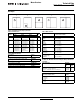
Technical Data Meter Breakers Effective: April 2002 Page 3 Product Selection Table 1.
Technical Data Page 4 Meter Breakers Effective: April 2002 Table 3. Combination Service Entrance Devices (EUSERC) Ampere Bypass Service kAIC Jaws DistribRating ution Main Wiring Knockout Branch DimenBreaker sions & Page Fig. Page Fig.
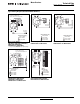
Technical Data Meter Breakers Effective: April 2002 Page 5 Box Styles B A C D E Figure 1. Five Different Styles (Shapes) of Product Table 5. Box Dimensions Box Number Table 7. Wire Size Chart Dimensions in Inches (mm) Height Width Depth Box Style 1 2 3 12-1/2 (317.5) 23-7/8 (606.4) 28-3/8 (720.7) 14-7/16 (366.7) 14-7/16 (366.7) 14-7/16 (366.7) 4 (101.6) 5-3/8 (136.5) 5-3/8 (136.5) A A A BR250 BR260 BR270 #14 – 4 kcmil #4 – 1/0 kcmil #4 – 1/0 kcmil 4 5 6 34-1/8 (866.8) 36-1/8 (917.
Technical Data Page 6 Meter Breakers Effective: April 2002 Typical Wiring Diagrams (Residential Meter Breakers) Bonded Neutral 1 2 3 4 5 6 7 8 9 10 11 12 13 14 23 24 25 26 27 28 29 30 31 32 15 35 16 36 17 37 18 38 19 39 20 40 21 41 22 42 33 34 Bonded Neutral Wiring Diagram Key #14-4 AWG #6-2/0 AWG B A Line N Line Wiring Diagram Key #14-2 AWG #14-4 AWG #6-2/0 AWG #6-250 AWG 1 3 2 4 7 8 11 12 B A N Bonded Neutral Figure 2.
Technical Data Meter Breakers Effective: April 2002 Page 7 Typical Wiring Diagrams (Residential Meter Breakers) Install 200A Maximum Service Disconnect Type CSR ➀ A B A B 1 A A B Line N Line N 34 1 Bonded Neutral B Wiring Diagram Key #14-1/0 AWG #14-6 AWG #14-1/0 AWG #6-250 AWG #14-2/0 AWG #14-2 AWG #6-250 AWG Figure 5. Catalog Numbers — CMBP200BTS, CMBB150BTS, CMBB200BTS, CMBEB150BTF, CMBEB150BTS, CMBEB200BTF and CMBEB200BTS Figure 7.
Technical Data Page 8 Meter Breakers Effective: April 2002 32 34 37 39 38 40 Bonded Neutral 9 11 13 15 17 19 21 23 1 3 5 7 9 11 2 6 8 10 12 Bonded Neutral 9 11 13 15 17 19 31 33 1 3 5 Bonded Neutral 2 4 6 1 3 5 Bonded Neutral Typical Wiring Diagrams (Residential Meter Breakers) Disconnect Type BW, BWH or CSR B A A B Line N Wiring Diagram Key #14-4 AWG #6-2/0 AWG #6-250 AWG Figure 10.
Technical Data Meter Breakers Effective: April 2002 Page 9 Typical Wiring Diagrams (Residential Meter Breakers) A B 200A Maximum Service Disconnect Type BW, BWH or CSR 200A Maximum Service Disconnect Type BW, BWH or CSR A B A B 1 2 34 56 A Line N B Neutral MCBK225 Kit for C/B Load Lugs A Line N B Wiring Diagram Key #14-1/0 AWG #14-6 AWG #14-2/0 AWG #6-250 AWG Figure 14.
Technical Data Page 10 Meter Breakers Effective: April 2002 Typical Wiring Diagrams (Residential Meter Breakers) A A B B A N B Bonded Neutral Line N Bonded Neutral N 200A Maximum Service Disconnect Type BW, BWH or CSR Bonded Neutral 1 2 3 4 1 2 5 6 3 4 7 8 5 9 10 7 8 11 12 9 10 11 12 Wiring Diagram Key #14-4 AWG #6-350 kcmil #6-2/0 AWG #6-300 kcmil #6-300 kcmil Figure 19.
Technical Data Meter Breakers Effective: April 2002 Page 11 Typical Wiring Diagrams (Residential Meter Breakers) Bonded Neutral 5TH Jaw Factory Installed on CMB1212B200BTSD and CMB1212P200BTSD Only A B Bonded Neutral A B 5th Jaw Factory Installed on CMB1212L200BTSD Only N A Line N B N Bonded Neutral Ground Bar 200A Maximum Service Disconnect Type CSR 1 2 3 4 5 6 7 8 9 10 11 12 2 3 4 5 6 7 8 9 10 11 12 Wiring Diagram Key #14-2/0 AWG #6-350 kcmil #6-300 kcmil Figure 26.
Technical Data Page 12 Meter Breakers Effective: April 2002 Typical Wiring Diagrams (Residential Meter Breakers) Factory Installed Service Disconnect Type CSR A A B B Bonded Neutral N Wiring Diagram Key #14-6 AWG #14-1/0 AWG #6 AWG-250 kcmil 1 3 5 7 9 11 13 15 17 19 21 23 25 27 29 31 33 35 37 39 41 Factory Installed Service Disconnect Type BW 2 4 6 8 10 12 14 16 18 20 22 24 26 28 30 32 34 36 38 40 42 Figure 29.
Technical Data Meter Breakers Effective: April 2002 Page 13 Typical Wiring Diagrams (Non-EUSERC Meter Breaker Design) A A B A B B Line N Included in MBB150BTSCR 125A Maximum Service Disconnect Type BR, or BRH 200A Maximum Service 1 3 2 4 Type BW, 8 10 12 Bonded Neutral 16 15 Wiring Diagram Key #14-4 AWG #6-350 kcmil #6-2/0 AWG #6-300 kcmil #6-300 kcmil Wiring Diagram Key #6-2/0 AWG #6-350 kcmil #6-250 kcmil #1-300 kcmil Figure 31.
Technical Data Page 14 Meter Breakers Effective: April 2002 Dimensions and Knockouts (Residential Meter Breakers) — Dimensions in Inches (mm) Keyhole Knockouts on Sides for Stucco Units Only. 3-1/2 (88.9) 5-5/16 (134.9) Top Stucco Top Surface 4-15/16 (125.4) 4-15/16 (125.4) Bottom Bottom Figure 36.
Technical Data Meter Breakers Effective: April 2002 Page 15 Dimensions and Knockouts (Residential Meter Breakers) — Dimensions in Inches (mm) Keyhole Knockouts on Sides for Stucco Units Only. 3-1/2 (88.9) 5-5/16 (134.9) Top Stucco Top Surface 4-15/16 (125.4) 4-15/16 (125.4) Bottom Bottom Figure 38.
Technical Data Page 16 Meter Breakers Effective: April 2002 Dimensions and Knockouts (Residential Meter Breakers) — Dimensions in Inches (mm) Keyhole Knockouts on Sides for Stucco Units Only. 3-1/2 (88.9) 5-5/16 (134.9) Top Surface Top Stucco 4-15/16 (125.4) 4-15/16 (125.4) Bottom Bottom Figure 40. Knockouts for Stucco and Surface Units Catalog Numbers — MBE1224B100TF, MBE1224B125TF, MBE2040B200TF and MBE2040P200TF Figure 41.
Technical Data Meter Breakers Effective: April 2002 Page 17 Dimensions and Knockouts (Residential Meter Breakers) — Dimensions in Inches (mm) 3-7/16 (87.3) Top Flush CMBE4242B200BTF MBE4040B200BTF 5-5/16 (134.9) 5-5/16 (134.9) Top Surface Top Surface 2-1/2-inch Hub 4-15/16 (125.4) 4-15/16 (125.4) Bottom Bottom CMBE4242B200BTS MBE4040B200BTS CMBE4242B200BSH MBE4040B200BSH Figure 42. Knockouts for Stucco and Surface Units Table 19. Top Endwall (Surface) Table 20.
Technical Data Page 18 Meter Breakers Effective: April 2002 Dimensions and Knockouts (Non-EUSERC Meter Breaker Design) — Dimensions in Inches (mm) 5-5/16 (134.9) 5-5/16 (134.9) Top Surface (Catalog Numbers with SC and SCR Suffix Only) Top Surface 4-15/16 (125.4) 4-15/16 (125.4) Bottom Bottom Figure 43.
Technical Data Meter Breakers Effective: April 2002 Type CH Residential 300 Ampere and 400 Ampere “House Panels” Product Description Page 19 Features, Benefits and Functions A “House Panel” is a service entrance device that consists of a meter socket and a distribution section. The unit is rated at 300 amperes or 400 amperes.
Technical Data Page 20 Meter Breakers Effective: April 2002 Technical Data and Specifications Typical Wiring Diagrams (Type CH Style House Panels) (OPTIONAL) FACTORY/FIELD INSTALLED 100A MAX. SERVICE DISCONNECT TYPE CHB FACTORY INSTALLED 200A SERVICE DISCONNECT 400 AMPS (320 AMPS CONTINUOUS) 400 AMPS (320 AMPS CONTINUOUS) EQUIPMENT GROUNDING TERMINALS EQUIPMENT GROUNDING TERMINALS 400 AMPS (320 AMPS CONTINUOUS) A N LINE A N B A N B LINE LINE BONDED NEUTRAL BONDED NEUTRAL Figure 45.
Technical Data Meter Breakers Effective: April 2002 Page 21 Dimensions and Knockouts (Type CH Style House Panels) — Dimensions in Inches 44.00 1-1/4, 1-1/2, 2 Knockouts per 50-1827-31 (1 Required) 1/2, 3/4 Knockouts per 50-1827-16 (8 Required) 1/2, 3/4, 1, 1-1/4 Knockouts per 50-26318 (2 Required) 29.750 I.D./I.D. 1-1/4, 1-1/2, 2, 2-1/2, 3 Knockouts per A50-25989 (2 Required) .656 ±.015 O.D./O.D. 3.000 2.266 ±.015 O.D. ±.015 .125 TYP. ±.015 O.D. 2-1/2, 3, 3-1/2, 4 Knockouts Per 50-27100 .
Technical Data Page 22 Meter Breakers Effective: April 2002 Type BR Residential 300 Ampere and 400 Ampere “House Panels” Product Description Features, Benefits and Functions A “House Panel” is a service entrance device that consists of a meter socket and a distribution section. The unit is rated at 300 amperes or 400 amperes.
Technical Data Meter Breakers Effective: April 2002 Page 23 Typical Wiring Diagrams (Type BR Style House Panels) (OPTIONAL) FACTORY/FIELD INSTALLED 200A MAX.
Technical Data Page 24 Meter Breakers Effective: April 2002 Typical Wiring Diagrams (Type BR Style House Panels) FACTORY INSTALLED 400A SERVICE DISCONNECT 400 AMPS (320 AMPS CONTINUOUS) A N B LINE 400 AMPS (320 AMPS CONTINUOUS) 1 2 3 4 5 7 9 11 13 15 17 19 21 23 25 27 29 31 33 35 37 39 41 6 8 10 12 14 16 18 20 22 24 26 28 30 32 34 36 38 40 42 EQUIPMENT GROUNDING TERMINALS N A B LINE 1 2 3 4 5 6 7 8 9 10 11 12 13 14 15 16 17 18 19 20 21 22 23 24 25 26 27 28 29
Technical Data Meter Breakers Effective: April 2002 Page 25 Dimensions and Knockouts (BR Style House Panels) — Dimensions in Inches 30.084 44.057 .625 2.250 1.750 2.875 .313 2.375 2.375 3.375 4.312 2.264 29.902 1/2, 3/4, Knockouts (9 Required) 1/2 (Optional), 3/4, 1, 1-1/4, 1-1/2 (3 Required) 2-1/2, 3, 3-1/2, 4 Knockouts 1.469 2.734 1.469 1-1/4 (Optional), 1-1/2, 2, 2-1/2 Knockouts (2 Required) 7.218 6.693 2.125 6.382 2.266 3.076 2.008 .494 1.373 7.166 5.406 2.546 2.546 3.062 4.
Technical Data Page 26 Meter Breakers Effective: April 2002 This page intentionally left blank. For more information visit: www.cutler-hammer.eaton.
Technical Data Meter Breakers Effective: April 2002 This page intentionally left blank. TD00502001E For more information visit: www.cutler-hammer.eaton.
Technical Data Page 28 Meter Breakers Effective: April 2002 Eaton Corporation Cutler-Hammer business unit 1000 Cherrington Parkway Moon Township, PA 15108-4312 USA tel: 1-800-525-2000 www.cutler-hammer.eaton.com © 2002 Eaton Corporation All Rights Reserved Printed in USA Publication No.