
User manual


Intelligent Technologies (
IT.
) D77B-DSNAP
14
Pub. No. MN05004001E
September 2002
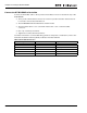
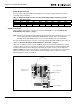
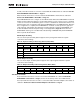
Default Output Assembly
The out of box output assembly (data mapped to the output registers within the system
controller) is the following:
Table 11: Output Assembly for Non-reversing Starter (E101, N101) and S751 Soft Start
FVR Motor Controller
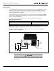
First, follow the instructions on how to mount the D77B-DSNAP as outlined in Mount the
D77B-DNSAP to the Starter on Page 7.
Note: The 45 mm and 54 mm frame
IT.
Starters will require the user to depress the cross over
cover locking tab while installing the D77B-DNSAP. Simply depress the tab while
inserting the D77B-DSNAP feet into the slot on the
IT.
Starter to ease installation.
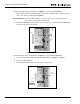
Second, follow the instruction on how to connect the Starter Terminal Adapter to the starter as
outlined in Connect the Starter Terminal Adapter to the Starter on Page 9.
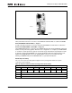
Third, the secondary contactor sensor (D77B-A2) needs to be installed. Install the secondary
contactor sensor on the second contactor just as you would install an auxiliary (align the feet
and slide towards the bottom). Using a screwdriver, pry up the connector access breakout
(Figure 1, Page 5) and remove the breakout. Insert the green connector that is connected via a
wire to the second contactor sensor into the breakout making sure to take notice of the
alignment tabs for proper orientation.
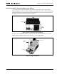
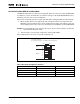
Figure 10: D77B-DSNAP-X2 on FVR
IT.
Starter
Instance 3: Basic Motor Starter
Byte Bit 7 Bit 6 Bit 5 Bit 4 Bit 3 Bit 2 Bit 1 Bit 0
0 Reserved Reserved Reserved Reserved Reserved FaultReset Reserved Run1
D77B-A2 Second
Contactor Sensor
Cover Locking Tab
Connector Breakout
Alignment Tab
Terminal Adapter
Jumper