Accessories & Modification Codes 16-1 Accessories & Modification Codes April 2008 Contents 16 Description Page Accessories IT. NEMA . . . . . . . . . . . . . . . . . . . . . . . . . . . . . . . . . . . . . . . . . . . . . . . . . . . Freedom NEMA . . . . . . . . . . . . . . . . . . . . . . . . . . . . . . . . . . . . . . . . . . . . . . Advantage NEMA . . . . . . . . . . . . . . . . . . . . . . . . . . . . . . . . . . . . . . . . . . . . A200 NEMA . . . . . . . . . . . . . . . . . . . . . . . . . . .
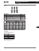
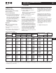
Accessories & Modification Codes Accessories 16-2 April 2008 IT. NEMA 16 IT. NEMA 16 Auxiliary Contacts Table 16-3. IEC Ratings Auxiliary Contacts are available for mounting on Eaton’s Cutler-Hammer Intelligent Technologies (IT.) ElectroMechanical Contactors and Starters. The various choices available for nonreversing models are shown in Tables 16-1 and 16-2, and their ratings in Tables 16-3 – 16-5.
Accessories & Modification Codes Accessories 16-3 April 2008 IT. NEMA Lug Kits 16 16 16 16 16 16 Table 16-8. Lug Kits NEMA Size Description Catalog Number 16 1 Contactor or Starter Line or Load (3 Lugs) EMLUGKTC 16 2 Contactor or Starter Line or Load EMLUGKTD 3, 4 Contactor Line or Load, Starter Line Starter Load EMLUGKTLE EMLUGKTTE 5 Contactor or Starter Line or Load, Horizontal Contactor or Starter Line or Load, Vertical EMLUGKTFA EMLUGKTFB 16 16 16 Table 16-9.
Accessories & Modification Codes Accessories 16-4 April 2008 Freedom NEMA 16 Freedom NEMA Contact Configuration Code 16 Auxiliary Contacts This two-digit code is found on the auxiliary contact to assist in identifying the specific contact configuration. The first digit indicates the quantity of NO contacts and the second indicates the quantity of NC contacts. 16 16 16 16 NEMA Sizes 00 – 2 The auxiliary contacts listed below are designed for installation on Freedom Series starters and contactors.
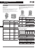
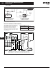
Accessories & Modification Codes Accessories 16-5 April 2008 Freedom NEMA Auxiliary Contact Location NEMA Sizes 3 – 8 NEMA Sizes 00 – 2 The sketches below illustrate the maximum number of auxiliary contacts that can be assembled to a contactor and their locations. The sketches below illustrate the maximum number of auxiliary contacts that can be assembled to a contactor or starter and their locations. Table 16-17. Auxiliary Contacts Catalog Number Size AN16 00 0–2 AN56 CN15 Table 16-18.
Accessories & Modification Codes Accessories 16-6 April 2008 Freedom NEMA 16 16 16 16 16 16 16 16 16 16 16 Heater Pack Selection Heater packs H2001B to H2017B and H2101B to H2117B are to be used only with Series B overload relays Catalog Numbers C306DN3B (Part No. 10-7016) and C306GN3B (Part No. 10-7020). The load lugs are built into the overload relay base Table 16-19.
Accessories & Modification Codes Accessories 16-7 April 2008 Freedom NEMA DC Magnet Coils Non-reversing Kit Consists of: ■ When Ordering Specify Conversion Kit for Field Assembly ■ Catalog Number Factory Installed DC Coil ■ For factory installed DC magnet coil on AC contactors or non-combination starters (open type only), substitute the Code Suffix from table below for the magnet coil identifier in the device Catalog Number.
Accessories & Modification Codes Accessories 16-8 April 2008 Freedom NEMA 16 A1 A2 16 Hold 16 NCI 16 3 A1 Pick-Up Hold 2 햲 2 3 NO 16 Important Incoming DC must be connected between A1 and Top A2 Terminal. A2 Top NCI Auxiliary Contact NO 햲 3 Pick-Up A2 Bottom 16 DC Coil Elementary Diagram for NEMA Sizes 1 – 3 Contactors and Starters 16 16 16 16 16 16 16 16 DC Coil Elementary Diagram for NEMA Sizes 00, 0, 4 & 5 Contactors and Starters Figure 16-4.
Accessories & Modification Codes Accessories 16-9 April 2008 Freedom NEMA 3-Pole Top Mounted Fuse Block Kit Mechanical Interlock and Reversing Kits NEMA Sizes 00 – 2 Mechanical interlocks and reversing kits are designed for field assembly of reversing contactors or starters from Freedom Series components. The Reversing Kits include a Mechanical Interlock, stabilizer bar and a pre-cut, trimmed and formed wire set. Auxiliary contacts, if required, must be ordered separately. See Page 16-4.
Accessories & Modification Codes Accessories 16-10 April 2008 Freedom NEMA 16 16 Solid-State Timers Locking Cover for Overload Relay — C306 Only Solid-State ON DELAY Timer — Side Mounted on Freedom Series NEMA 00 – 2 and C25D, C25E and C25F Frame Snap-on transparent or opaque plastic panel for covering access port to the overload relay trip setting dial — helps prevent accidental or unauthorized changes to trip and reset setting.
Accessories & Modification Codes Accessories 16-11 April 2008 Freedom NEMA ■ Finger Protection Shields NEMA Sizes 3 – 5 Snap-on shields for both contactors and starters provide Type IP20 Finger Protection. Prevents accidental contact with line/load terminals. This device mounts on top of any side mounted auxiliary contact on Freedom Series NEMA Sizes 3 – 5 and lighting contactors 100 – 300A.
Accessories & Modification Codes Accessories 16-12 April 2008 Freedom NEMA, Advantage NEMA 16 Fuse Clips 16 16 16 16 16 C351 Fuse Clip Kit 16 16 16 Table 16-42.
Accessories & Modification Codes Accessories 16-13 April 2008 Freedom NEMA, Advantage NEMA Control Power Transformer Kits The transformer kit consists of: Combination Starters ■ Most combination starters have space for standard size (and 100 VA extra capacity) control power transformers. The panels are pre-drilled for mounting.
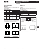
Accessories & Modification Codes Accessories 16-14 April 2008 Advantage NEMA 16 DeviceNet™ Communications Module 16 16 16 16 16 16 16 16 16 16 16 16 16 16 16 16 16 16 16 16 DeviceNet Module The DeviceNet Communications module (Catalog Number WPONIDNA) is designed to plug into the Advantage with the attached cable and plug. The module can be snapped onto the top or bottom of the Advantage unit. It can also be mounted separately using the mounting plate assembly (Catalog Number WPONIBASE).
Accessories & Modification Codes Accessories 16-15 April 2008 Advantage NEMA OL Selection DIP Switch Window Internal Trip Indicator ■ Mount remotely up to 6 ft. away Unit completely assembled including legend plate ■ Available also in reset-only form — no trip indication provided ■ Table 16-55. Remote Pushbuttons Description DIP Switch Window Internal Trip Indicator ■ Overload condition indication — indicated by blinking light ■ Trip condition — indicated by solid light Table 16-53.
Accessories & Modification Codes Accessories 16-16 April 2008 Advantage NEMA An additional Metering Module replaces conventional ammeters (three-phase), replaces reset mechanisms and displays trip cause and data, control voltage and status.
Accessories & Modification Codes Accessories 16-17 April 2008 Advantage NEMA Reversing and 2-Speed Pushbutton Modules 2.25 (57.2) Status Only ■ RES Reset Run Fwd 3.5 (88.
Accessories & Modification Codes Accessories 16-18 April 2008 A200 NEMA 16 A200 NEMA 16 Factory Modifications 16 16 Table 16-57.
Accessories & Modification Codes Accessories 16-19 April 2008 A200 NEMA Heater Selection General Information on Heater Coil Selection For maximum motor protection and compliance with Article 430-32 of the National Electrical Code, select heater coils from the tables in this section on the basis of motor nameplate full load current. When the full load current is unknown, selection may be made on the basis of average full load currents.
Accessories & Modification Codes Accessories 16-20 April 2008 A200 NEMA 16 16 Table 16-62. Heater Selection — Type A and B Overload Relays, Sizes 0, 1 and 2 Size Starter 16 Non-compensated Open Starters and Heater Ambient Comp.
Accessories & Modification Codes Accessories 16-21 April 2008 A200 NEMA F-56 Fuse Block B3NO Bell Alarm Contact ■ ■ ■ ■ ■ ■ SS-56 Surge Suppressor SS-56 Surge Suppressor ■ ■ ■ ■ ■ ■ Designed to be used with magnetic motor controllers through Size 4 in 120V, 60 Hz control circuit applications where electronic equipment is used. Steady State Coil Volts: 120, 60 Hz, RMS Peak Input Volts: 169.6, 60 Hz, Max. Amplitude Max.
Accessories & Modification Codes Accessories 16-22 April 2008 A200 NEMA 16 16 Replacement Auxiliary Contacts Mechanical Interlocks Table 16-70. Replacement Auxiliary Contacts Table 16-73.
Accessories & Modification Codes Accessories 16-23 April 2008 XT IEC XT IEC 16 Auxiliary Contacts Notes: The 7 – 32A XTCE Contactors have positively driven contacts between the integrated auxiliary contact and the auxiliary contact module as well as within the auxiliary contact modules. Front mounted snap-on auxiliary contacts for XT contactors are available with screw or spring cage terminals in a variety of contact configurations.
Accessories & Modification Codes Accessories 16-24 April 2008 XT IEC 16 Table 16-77. Auxiliary Contacts Conventional Thermal Current, Open at 60°C Ith = Ie, AC-1 in Amps 16 16 Poles Contact Configuration 16 2 2NO 16 2 1NO-1NC 16 2 2NC 16 2 1NOE-1NCL 16 2 1NO-1NC Circuit Symbol Pkg. Qty.
Accessories & Modification Codes Accessories 16-25 April 2008 XT IEC Table 16-77. Auxiliary Contacts (Continued) Conventional Thermal Current, Open at 60°C Ith = Ie, AC-1 in Amps Poles Contact Configuration Circuit Symbol Pkg. Qty.
Accessories & Modification Codes Accessories 16-26 April 2008 XT IEC Table 16-78. Side Mount Auxiliary Contacts for Frame D – R, 40 – 2000A 16 Poles Contact Configuration 10 2 1NO-1NC 10 2 1NOE-1NCL Circuit Symbol 14 17 61 83 62 71 84 16 54 26 72 16 47 53 25 35 1NO-1NC 48 2 22 36 10 43 18 16 31 16 21 13 16 16 Pkg. Qty.
Accessories & Modification Codes Accessories 16-27 April 2008 XT IEC 16 XTMC6A... – XTMC9A... XTCE007B... – XTCE032C... 16 16 XTMCXF...A... XTCEXF...C... 2-Pole or 4-Pole 16 16 16 Frame A – B 16 XTCEXF...C... 2-Pole or 4-Pole XTCEXSCC11 XTCE007B... – XTCE032C... or 16 16 XTCE018C... – XTCE032C... + 16 16 Frame C 16 + or XTCEXF...G... 4-Pole + + 16 XTCEXSBN11 XTCEXF...G... 2-Pole XTCEXSBN11 + 16 XTCE040D... – XTCE065D... XTCEXSBN11 XTCEXSBN11 XTCE040D... – XTCE065D...
Accessories & Modification Codes Accessories 16-28 April 2008 Enclosures 16 Type 1 Enclosures Table 16-80. Type 1 Enclosures — NEMA (Freedom and IT.
Accessories & Modification Codes Accessories 16-29 April 2008 Enclosures Type 3R, 4X and 12 Enclosures 16 Table 16-82. Type 3R, 4X and 12 Enclosures — NEMA (Freedom and IT.
Accessories & Modification Codes Accessories 16-30 April 2008 Lighting Contactors 16 Lighting Contactors 16 Electrically Held Base Contactor for C30CN/ECC 16 The C30CNE20_0 Electrically Held Base Contactor contains a 2NO power pole as standard and will allow the addition of power poles to build an Electrically Held Contactor up to 12 poles maximum. A Mechanically Held Module Kit can also be added to convert the Electrically Held Contactor into a Mechanically Held Contactor in the field.
Accessories & Modification Codes Accessories 16-31 April 2008 Lighting Contactors Auxiliary Contacts for C30CN/ECC Transient Suppressor Kits for CN35/ECL A Mechanically Held Contactor with a 2-wire control module uses 1NC auxiliary contact as standard for the control wiring circuit. The Mechanically Held Contactor with a 3-wire control module uses 1NO-1NC auxiliary contacts as standard for the control wiring circuit. See Table 16-90 for possible additional auxiliary contact configurations.
16-32 Accessories & Modification Codes Accessories April 2008 Lighting Contactors 16 16 16 16 16 16 16 16 16 16 16 16 Auxiliary Contacts for CN35/ECL CN35 Lighting Contactors include a 1NO maintaining auxiliary contact mounted on right hand side (on 10A, 2- and 3-pole devices, auxiliary contact occupies 4th power pole position — no increase in width). The 10 – 60A devices will accept additional auxiliary contacts on the top and/or sides.
Accessories & Modification Codes Accessories 16-33 April 2008 Lighting Contactors Auxiliary Contact Location for CN35/ECL Pneumatic Timers — Top Mounted for CN35/ECL 16 16 Auxiliary Contacts — Mounting Positions The sketches below illustrate the maximum number of auxiliary contacts that can be assembled to a contactor and their locations in standard enclosures. 16 16 16 Table 16-97.
Accessories & Modification Codes Accessories 16-34 April 2008 Lighting Contactors 16 R-56 Interposing Relay for A202/ECL 16 The R-56AA interposing relay is a low energy solid-state device with a single NO solid-state contact. It can be used as a 120V AC control relay, and will operate on as little as 40V AC input. Is useful in applications requiring long control wiring runs where excessive voltage drop would prevent the contactor or relay from energizing.
Accessories & Modification Codes Accessories 16-35 April 2008 Lighting Contactors Replacement Auxiliary Contacts for A202/ECL DC Coil Conversion Kits for A202/ECL Table 16-107. Replacement Auxiliary Contacts Kits listed below include all necessary parts to convert from AC to DC control including the DC coil with built-in diode, rectifier, auxiliary interlock and all mounting hardware. Contactor Size Contact Arrangement Aux. Elect.
Accessories & Modification Codes Accessories 16-36 April 2008 IT. Solid-State Soft Starters 16 IT. Solid-State Soft Starters 16 Auxiliary Contacts for S752 16 16 16 16 16 16 16 16 The S752 allows for the use of top mounted auxiliary contacts. These contacts can be used for up-to-speed indication. Table 16-110. S752 Auxiliary Contacts Poles Catalog Number 1NO 1NC 1NO/1NC EMA13 EMA14 EMA15 2NO 2NC 1NO/1NC Logic Level EMA16 EMA17 EMA70 Table 16-111.
Accessories & Modification Codes Accessories 16-37 April 2008 IT. Solid-State Soft Starters Lug Kits for S801/S811 Adapter Plates The 200 mm and 290 mm soft starters do not include lugs. The 200 mm and 290 mm soft starters each have different lug options based on your wiring needs. Each lug kit contains three lugs which can be mounted on either the load or line side. The Adapter Plate allows customers to retrofit a V-Frame 290 mm Soft Starter with the U-Frame 200 mm Soft Starter.
16-38 Accessories & Modification Codes Accessories April 2008 Adjustable Frequency Drives 16 16 MVX900 Microdrives Table 16-125.
Accessories & Modification Codes Accessories 16-39 April 2008 NEMA Vacuum Break Control NEMA Vacuum Break Control Heater Coils Table 16-129. Heater Coil Selection for Type B Overload Relay Lug Sizes Motor Full Load Current in Amperes for Use with 3 Heaters Only ■ Size 4 — 12 – 4/0 ■ NEMA Size 5 & 6 and 320A, 540A & 610A — Supplied without Line or Load Lugs.
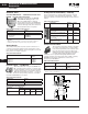
16-40 Accessories & Modification Codes Modification Codes April 2008 16 16 16 16 Modification Codes Table 16-130. A — Ammeters, Auxiliary Contacts, Accelerating Relays, Autotransformers Table 16-130.
Accessories & Modification Codes Modification Codes 16-41 April 2008 Table 16-132. C — Control Power Transformer, IT. Power Supplies, Control Relays, Cover Control (not elsewhere defined), Current Transformers, Compelling Relay, Control Wiring, Control Circuit Breaker, Separate Control, Customer-Supplied Components, Custom for Advantage, Contactors, Counter, E-Stop Relay, DC/AC Interface, Separate Source Disconnect, Bypass Contactors Table 16-132. C — Control Power Transformer, IT.
Accessories & Modification Codes Modification Codes 16-42 April 2008 16 16 16 16 Table 16-133. D — Device Labels, Deceleration Relay, Drain and Breather, Duplex Modifications Modification Catalog Number Suffix Description Device Labels D1 (Each Label) Decel. Relay D2 2-Speed Table 16-134.
Accessories & Modification Codes Modification Codes 16-43 April 2008 Table 16-139. L — Labels, Line and Load Reactors, Table 16-136.
Accessories & Modification Codes Modification Codes 16-44 April 2008 16 16 Table 16-141. P — Pilot Lights, Pushbuttons, Phase Relays, Potential Transformers, Power Factor Correction Capacitors, Program Timer, Percentage Timer, Photocell Table 16-141.
Accessories & Modification Codes Modification Codes 16-45 April 2008 Table 16-142. Q — IQ Products, DN50 Modification IQ Products IQ Data Metering Module DN50 Table 16-143.
Accessories & Modification Codes Modification Codes 16-46 April 2008 16 16 16 16 Table 16-144.
Accessories & Modification Codes Modification Codes 16-47 April 2008 Table 16-145. T — Timers, Time Delay Relays, Terminal Blocks, Terminal Points, Ring Lug Connections (Continued) Table 16-147.