
Technical data


April 2008
PG03300001E For more information visit: www.eaton.com
16-7
Accessories & Modification Codes
16
16
16
16
16
16
16
16
16
16
16
16
16
16
16
16
16
16
16
16
16
16
16
16
16
16
16
16
16
16
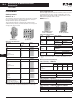
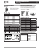
Accessories
Freedom NEMA
DC Magnet Coils
When Ordering Specify
Conversion Kit for Field Assembly
■ Catalog Number
Factory Installed DC Coil
■ For factory installed DC magnet coil
on AC contactors or non-combina-
tion starters (open type only), sub-
stitute the Code Suffix from table
below for the magnet coil identifier
in the device Catalog Number.
EXAMPLE: For Size 0 AC contactor
with a 24V DC coil, change
CN15BN3AC to CN15BN3T1C.
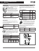
Application
■ Connect for separate control
■ Not for use with cover control
switch operators
■ Use twin break, heavy-duty pilot
devices
■ Designed for +10%, -20% rated volt-
age, continuous duty operation
Non-reversing Kit Consists of:
■ 1 Encapsulated DC magnet coil
■ 1 NCI or NO/NCI side mounted
auxiliary contact
Note: These kits are supplied with a NO/
NCI side mounted auxiliary contact in
place of the NCI contact.
■ 2 Blue colored connection wires
■ 1 Instruction publication
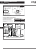
Operation
These DC coil kits have separate pick-
up and seal windings. A special (side
mounted) early-break NCI auxiliary
contact is used to either disconnect the
pick-up winding or insert the seal
winding in series with the pick-up
winding, depending on the frame size
of the contactor. DC coil kits come in
two styles, a suffix 1 and a suffix 4. The
1 suffix contains only the special (side
mounted) early break NCI auxiliary
contact. The 4 suffix contains a NO
contact in the same package as the
special (side mounted) early-break NCI
auxiliary contact.
Note: For NEMA Sizes 00 and 0 contactors
may utilize either suffix 1 or 4 DC coil kits;
starters may utilize suffix 4 DC coil kits only.
For NEMA Sizes 1 and 2, both contactors
and starters may utilize a suffix 4 DC coil
kit only.
On the above sizes only, when the
special auxiliary package is mounted
on the side of a contactor or starter,
no standard auxiliary contact may be
mounted on the same side.
Note: For NEMA Sizes 3 – 5, the special coil
NCI clearing contact is an add-on auxiliary
(must mount on a base mount auxiliary
contact; normally a 1NO). This arrangement
will normally account for two of the three
contact positions on the side of each con-
tactor or starter.
See Figure 16-4, Page 16-8.
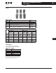
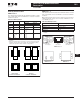
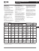
Table 16-22. Product Selection
These kits are supplied with a NO/NCI side mounted auxiliary contact in place of the NCI contact.
Kit does not include mechanical interlock or crossover wiring. Two NO/NCI top mounted auxiliary contacts are supplied for electrical interlocking.
Factory installed DC coils on NEMA contactors and starters include a NO/NC top mounted auxiliary contact on each contactor for electrical interlocking.
Available factory assembled only.
Contactor or
Starter Size
Conversion Data Complete Conversion Kit Factory
Installed
Volts Magnet Coil NCI
Interlock
Number
NEMA Coil
Number
Amps
P.U./Seal
Watts
P.U./Seal
Catalog
Number
Ship Wt.
Lbs. (kg)
Code
Suffix
Non-reversing — Kit includes NCI Side Mounted Auxiliary Contact
00 and 0
CN35 – A, B, D
D15 Relays
12
24
48
120
9-2988-11
9-2988-12
9-2988-13
9-2988-14
6.4/.28
3.2/.14
1.6/.07
.64/.028
76.8/3.36
76.8/3.36
76.8/3.36
76.8/3.36
C320KGD1
C320KGD1
C320KGD1
C320KGD1
C335KD3R1
C335KD3T1
C335KD3W1
C335KD3A1
1.0 (.5) R1
T1
W1
A1
00 and 0
CN35 – A, B, D
D15 Relays
12
24
48
120
9-2988-11
9-2988-12
9-2988-13
9-2988-14
6.4/.28
3.2/.14
1.6/.07
.64/.028
76.8/3.36
76.8/3.36
76.8/3.36
76.8/3.36
C320KGD2
C320KGD2
C320KGD2
C320KGD2
C335KD3R4
C335KD3T4
C335KD3W4
C335KD3A4
1.0 (.5) R4
T4
W4
A4
1 and 2
CN35 – G
12
24
48
120
9-2990-1
9-2990-2
9-2990-3
9-2990-4
15.4/.42
7.7/.21
3.9/.11
1.5/.041
185/4.98
185/4.96
185/5.04
185/4.87
C320KGD5
C320KGD5
C320KGD5
C320KGD5
C335KD4R4
C335KD4T4
C335KD4W4
C335KD4A4
1.0 (.5) R4
T4
W4
A4
3
CN35 – K
12
24
48
120
9-3002-1
9-3002-2
9-3002-3
9-3002-4
24/.40
12/.20
6.1/.097
2.5/.038
293/4.84
288/4.75
295/4.67
298/4.57
C320KGD3
C320KGD3
C320KGD3
C320KGD3
C335KD5R1
C335KD5T1
C335KD5W1
C335KD5A1
2.0 (.9) R1
T1
W1
A1
4 and 5
CN35 – N, S
24
48
120
240
9-2026-4
9-2026-3
9-2026-2
9-2026-1
18/.22
9/.11
3.3/.05
1.7/.02
400/5.3
400/5.2
450/5.4
440/4.9
C320KGD3
C320KGD3
C320KGD3
C320KGD3
C335KA3T1
C335KA3W1
C335KA3A1
C335KA3B1
2.5 (1.1) T1B
W1B
A1B
B1B
Reversing
00 and 0
CN35 – A, B, D
D15 Relays
12
24
48
120
9-2988-1
9-2988-2
9-2988-3
9-2988-4
6.4/.28
3.2/.14
1.6/.07
.64/.028
76.8/3.36
76.8/3.36
76.8/3.36
76.8/3.36
C320KGD1
C320KGD1
C320KGD1
C320KGD1
C335KD3R1
C335KD3T1
C335KD3W1
C335KD3A1
1.0 (0.9) R1
T1
W1
A1
1 and 2
CN35 – G
12
24
48
120
9-2990-1
9-2990-2
9-2990-3
9-2990-4
15.4/.42
7.7/.21
3.9/.11
1.5/.041
185/4.98
185/4.96
185/5.04
185/4.87
C320KGD3
C320KGD3
C320KGD3
C320KGD3
— R1
T1
W1
A1