
Firmware Manual

Appendix A—Description of Parameters
154 PowerXL DG1 Series Adjustable Frequency Drives MN040004EN—March 2014 www.eaton.com
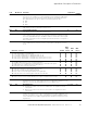
P7.20 261 Skip F3 High Lim 1, 2, 3, 4 RW
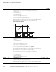
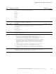
In some systems it may be necessary to avoid certain frequencies because of
mechanical resonance problems. With these parameters, limits are set for the “skip
frequency” regions. The frequency converter will skip the set frequencies, ramp
time will be the same. See Figure 54.
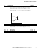
Figure 54. Example of Skip Frequency Area Setting
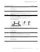
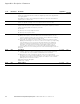
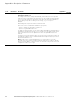
P7.21 264 PH Accel/Decel Ramp 1, 2, 3, 4 RW
Defines the acceleration/deceleration time when the output frequency is between
the selected prohibit frequency range limits. The ramping speed (selected
acceleration/deceleration time 1 or 2) is multiplied with this factor. e.g., value 0.1
makes the acceleration time 10 times shorter than outside the prohibit frequency
range limits.
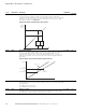
Figure 55. Ramp Speed Scaling between Skip Frequencies
P7.22 267 Power Loss Function
This enables the drive to reduce output voltage to the motor to keep the drive up as
long as possible.
1, 2, 3, 4 RW
1 Enable power loss function
0 Disable power loss function
P7.23 268 Power Loss Time 1, 2, 3, 4 RW
Allowable power loss max time before the drive shuts down. If AC input voltage
recovers before this time setting, drive will continue to work.
Code Modbus ID Parameter Application
RO/RW
Output
Frequency
(Hz)
P7.15
P7.17
P7.19
P7.16
P7.18
P7.20
Reference (Hz)
fout (Hz)
Time(s)
P7.21 = 1.2
P7.21 = 0.2
P7.15
(P7.17; P7.19)
P7.16
(P7.18; P7.20)