
Firmware Manual


Appendix A—Description of Parameters
162 PowerXL DG1 Series Adjustable Frequency Drives MN040004EN—March 2014 www.eaton.com
P9.7 309 Ground Fault 1, 2, 3, 4 RW
Earth fault protection ensures that the sum of the motor phase currents is zero. The
overcurrent protection is always working and protects the frequency converter from
earth faults with high currents. Frequency Converter will cores pond the setting
below.
0 No response
1 Warning
2 Fault, stop mode after fault according to P7.10
3 Fault, stop mode after fault always by coasting
P9.8 310 Motor Therm Prot 1, 2, 3, 4 RW
If tripping is selected, the drive will stop and activate the fault stage based off the%
calculated motor temperature. Deactivating this protection, i.e., setting parameter to
0, will reset the thermal stage of the motor to 0%.
0 No response
1 Warning
2 Fault, stop mode after fault according to ID506
3 Fault, stop mode after fault always by coasting
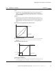
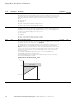
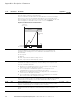
P9.9 311 Motor Therm F0 Current 1, 2, 3, 4 RW
The current can be set between 0–150.0% x I
n
Motor. This parameter sets the value
for thermal current at zero frequency. See Figure 58.
The default value is set assuming that there is no external fan cooling the motor. If
an external fan is used, this parameter Different settings: 90% (or even higher).
Note: The value is set as a percentage of the motor nameplate data, P1.5 (nominal
current of the motor), not the drive’s nominal output current. The motor’s nominal
current is the current that the motor can withstand in direct on-line use without
being overheated.
If you change the parameter Nominal current of motor, this parameter is
automatically restored to the default value.
Setting this parameter does not affect the maximum output current of the drive,
which is determined by P1.16 alone.
Figure 58. Motor Thermal Current I
T
Curve
Code Modbus ID Parameter Application
RO/RW
100%
0
Overload Area
P9.9 = 40%
Cooling
P
f
f
n
I
T