
Firmware Manual


Appendix A—Description of Parameters
170 PowerXL DG1 Series Adjustable Frequency Drives MN040004EN—March 2014 www.eaton.com
P10.6 1300 PID1 Process Unit Min 2, 3, 4 RW
Minimum process unit Value.
P10.7 1302 PID1 Process Unit Decimal 2, 3, 4 RW
Decimal places in process unit Value.
P10.8 1303 PID1 Error Inversion 2, 3, 4 RW
0 Normal, If feedback is less than setpoint, PID controller output increases
1 Inverted, If feedback is less than setpoint, PID controller output decreases
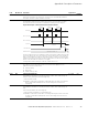
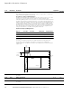
P10.9 1304 PID1 Dead Band 2, 3, 4 RW
PID Dead band around setpoint in process units. The PID output is locked if the
feedback stays within the deadband area for a delay.
P10.10 1306 PID1 Dead Band Delay 2, 3, 4 RW
If the feedback stays within the dead band area for a delay time, output is locked.
P10.11 1307 PID1 Keypad Set Point 1 2, 3, 4 RW
Keypad setpoint 1.
P10.12 1309 PID1 Keypad Set Point 2 2, 3, 4 RW
Keypad setpoint 2.
P10.13 1311 PID1 Ramp Time 2, 3, 4 RW
Defines the rising and falling ramp times for setpoint changes.
P10.14 1312 PID1 Set Point 1 Source 2, 3, 4 RW
Defines source of the setpoint.
P10.15 1313 PID1 Set Point 1 Min 2, 3, 4 RW
Defines Minimum Value.
P10.16 1314 PID1 Set Point 1 Max 2, 3, 4 RW
Defines Maximum Value.
P10.17 1315 PID1 Set Point 1 Sleep Enable 2, 3, 4 RW
Enable PID Set Point Sleep mode.
P10.18 1316 PID1 Set Point 1 Sleep Freq 2, 3, 4 RW
Drive goes to sleep mode when the output frequency stays below this limit for a
time greater than that defined by parameter Sleep delay.
P10.19 1317 PID1 Set Point 1 Sleep Delay 2, 3, 4 RW
The minimum amount of time the frequency has to remain below the sleep level
before the drive is stopped.
P10.20 1318 PID1 Set Point 1 Wake-Up Level 2, 3, 4 RW
Defines the level for the PID feedback value wake-up supervision. Uses selected
process units.
P10.21 1320 PID1 Set Point 1 Boost 2, 3, 4 RW
The setpoint can be boosted with a digital input.
P10.22 1321 PID1 Set Point 2 Source 2, 3, 4 RW
Defines source of the setpoint.
P10.23 1322 PID1 Set Point 2 Min 2, 3, 4 RW
Defines Minimum Value.
P10.24 1323 PID1 Set Point 2 Max 2, 3, 4 RW
Defines Maximum Value.
P10.25 1324 PID1 Set Point 2 Sleep Enable 2, 3, 4 RW
Enable PID sleep function.
P10.26 1325 PID1 Set Point2 Sleep Freq 2, 3, 4 RW
Drive goes to sleep mode when the output frequency stays below this limit for a
time greater than that defined by parameter Sleep delay.
Code Modbus ID Parameter Application
RO/RW