
Installation Manual

Chapter 3—Product Overview
DG1 Series VFD MN040002EN—March 2014 www.eaton.com 13
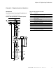
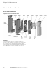
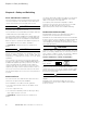
Figure 7. Block Diagram, Elements of DG1 Frequency Inverters
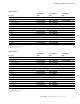
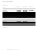
Table 12. Elements of DG1 Frequency Inverters
Item No. Description
1 Supply L1, L2 L3, PE, input supply voltage U
LN = Ue at 50/60 Hz:
DG1-32: 230V class, three-phase input connection (3 AC 230V/240V)
DG1-34: 400V class, three-phase input connection (3 AC 400V/480V)
2 Internal interference suppression filter, category C2 to IEC/EN 61800-3
EMC-connection of internal interference suppression filter to PE
3 Rectifier bridge, converts the AC voltage of the electrical network into DC voltage
4 DC link with charging resistor, capacitor and switching mode power supply unit
(SMPS = Switching Mode Power Supply):
DC link voltage U
DC with three-phase input connection (3 AC): UDC = 1.41 x ULN
5 Inverter. The IGBT based inverter converts the DC voltage of the DC link (UDC) into a three-phase AC voltage (U2) with variable amplitude
and frequency (f2). Sinusoidal pulse width modulation (PWM) with V/f control can be switched to speed control with slip compensation
6 Motor connection U/T1, V/T2, W/T3 with output voltage U2 (0–100% U
e) and output frequency f2 (0–400 Hz) output current (I2):
DG1-32: 3.7A to 261A
DG1-34: 2.2A to 261A
100% at an ambient temperature of 122°F (50°C) with an overload capacity of 150% for 60 s every 600 s and a starting current
of 200% for 2 s every 20 s
7 Keypad with control buttons, graphic display, control voltage, control signal terminals, micro-switches, and interface for the
PC interface module (option)
8 Three-phase asynchronous motor, variable speed control of three-phase asynchronous motor for assigned motor shaft power values (P2):
DG1-32: 0.55 kW to 75 kW (230V, 50 Hz) or 0.75 hp to 100 hp (240V, 60 Hz)
DG1-34: 0.75 kW to 150 kW (400V, 50 Hz) or 1 hp to 200 hp (460V, 60 Hz)
9 DC link—chokes, to minimize current harmonics