
Installation Manual


Appendix B—Installation Guidelines
DG1 Series VFD MN040002EN—March 2014 www.eaton.com 49
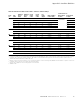
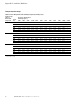
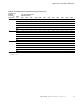
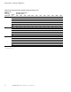
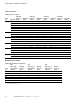
Table 32. International Cable and Fuse Sizes—380 Vac to 440 Vac Ratings
Notes
1
Line and motor cable size is selected according to IEC60364–5–52:2009 Table B.52.4 for copper conductor with PVC insulation with a wiring condition of ambient
temperature 30°C in air and an installation method of “B2” (cables in conduit and cable trunking systems). For other wiring conditions, please refer to the
standard of IEC60364–5–52:2009 for suitable cable sizes.
2
Earthing conductor size is determined by the cross–sectional area of phase conductors according to IEC/EN61800–5–1:2007 Table 5. So if phase conductor size
is changed, earthing conductor size should also be changed accordingly.
3
If power cubes or bypass are used, a Class gG/gL fuse is recommended.
4
Available in 2015.
Frame
Size
Amp
Suffix
400V Input
Current
(CT/I
H
)
400V Input
Current
(VT/I
L
)
Current
(CT/I
H
)
at 50°C
Current
(VT/I
L
)
at 40°C
Fuse
Rating
(gG/gL)
Mains and Motor
Cable Cu (mm
2
)
Terminal Cable Size
Main Terminal
Cu (mm
2
)
Earth Terminal
Cu (mm
2
)
FR1 2D2 2.0 3.1 2.2 3.3 6 3*1.5+1.5 0.2–6 solid or
0.2–4 stranded
0.75–6
3D3 3.1 4 3.3 4.3 6 3*1.5+1.5 0.75–6
4D3 4.0 5.2 4.3 5.6 10 3*1.5+1.5 0.75–6
5D6 5.2 7.1 5.6 7.6 16 3*1.5+1.5 0.75–6
7D6 7.1 8.4 7.6 9 16 3*1.5+1.5 0.75–6
9D0 8.4 11.2 9 12 16 3*1.5+1.5 0.75–6
FR2 012 11.2 15 12 16 20 3*4+4 0.5–16 4–16
016 14.9 21.5 16 23 25 3*4+4 0.5–16 4–16
023 21.4 29 23 31 32 3*6+6 0.5–16 4–16
FR3 031 28.8 35.2 31 38 40 3*16+16 16–35 2.5–25
038 35.3 42.6 38 46 50 3*16+16 16–35 2.5–25
046 42.8 55.7 46 61 63 3*16+16 16–35 2.5–25
FR4 061 56.7 65.7 61 72 80 3*25+16 16–50 6–50
072 66.9 79.4 72 87 100 3*35+16 16–50 6–50
087 80.9 97 87 105 125 3*50+25 16–50 6–50
FR5 105 97.6 129 105 140 160 3*70+35 50–185 10–120
140 130.1 157 140 170 200 3*95+50 50–185 10–120
170 158.0 189 170 205 250 3*120+70 50–185 10–120
FR6 205 190.6
4
205 261 315 3*240+120
44
261
44
261 310 350 2*(3*95+50)
44