
Installation Manual


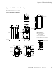
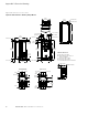

Appendix C—Dimension Drawings
56 DG1 Series VFD MN040002EN—March 2014 www.eaton.com
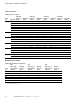
Approximate Dimensions in Inches (mm)
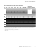
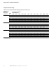
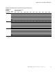
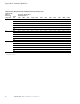
Figure 32. FR1 Dimension Drawing Flange Mount
REMOTERUNFAULT
STOP
BACK
RESET
LOCAL
REMOTE
OK
START
C 3.94 (100.0)
D 1.97 (50.0)
A/B 0.79 (20.0)
A = Air gap around drive
B = Space between two drives or
drive and cabinet
C = Free space above drive
D = Free space below drive
Minimum Dimensions
For Class IP54, dimension A and B = 0
4.80
(122.0)
0.28 (7.0)
Ø 0.28 (7.0)
3.94
(100.0)
Ø 0.47 (12.0)
12.64
(321.0)
Ø 0.26 (6.5)
7.01 (178.0)
0.26 (6.5)
6.31 (160.4)
3.94 (100.0)
2.84 (72.2)
1.40
(35.5)
10.63
(270.0)
3.83
(97.2)
13.94
(354.0)
6.31 (160.4)
10.63
(270.0)
1.40 (35.0)
1.20 (30.5)
1.70
(44.0)
Ø 0.89
(22.5)
1.40 (35.5)
1.70
(44.0)
1.30 (32.5) 1.30 (32.5)
2.20
(57.0)
3.90
(100.3)
0.85 (21.5)
11.50
(292.0)
7.89
(200.4)
0.78
(19.9)
1.10
(28.0)
0.53 (13.5)
2.60 (66.0)
5.31
(134.9)
Type 1/12 ULIP21/IP54 Metric
6-Ø 22.5
35.0
57.0
100.3
44.0
44.0
35.0
32.5 32.5