PowerXL DG1 Series VFD Quick Start Guide Effective March 2014 New Information CONTENTS Step 1—PowerXL DG1 Series Overview . . . . . . . Step 2—Keypad Operation Overview . . . . . . . . . Step 3—Menu Navigation . . . . . . . . . . . . . . . . . . Step 4—Startup Wizard . . . . . . . . . . . . . . . . . . . . Step 5—Standard Parameter List . . . . . . . . . . . . Step 6—Faults and Warning Codes . . . . . . . . . . .
Step 1—PowerXL DG1 Series Overview Step 1—PowerXL DG1 Series Overview This chapter describes the purpose and contents of this manual, the receiving inspection recommendations and the DG1 Series Open Drive catalog numbering system. Real Time Clock Battery Activation How to Use this Manual Simply remove the primary drive cover, locate the RTC battery directly below the keypad, and connect the white 2-wire connector to the receptacle on the control board.
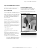
Step 1—PowerXL DG1 Series Overview Rating Label Keypad Overview Figure 2. Rating Label Figure 3. Keypad and Display Programmable Soft Key 2 Programmable Soft Key 1 Increase Value Scroll Menu Up Change Control Place Between Local and Remote Back/Reset Button Move Cursor Right Start Button Stop Button Move Cursor Decrease Value Left Scroll Menu Down Enter Menu Confirm Selection Contains SN, PN, Type, Date Contains EAN Code Contains NAED Code Date Code: 20131118 Carton Labels (U.S.
Step 2—Keypad Operation Overview Step 2—Keypad Operation Overview The keypad is the interface between the drive and the user. It features an LCD display, 3 LED lights and 11 buttons. With the control keypad, it is possible to control the speed of a motor, to supervise the state of the equipment and to set the frequency converter’s parameters. See Figure 3. Keypad Buttons Buttons Description Table 2.
Step 2—Keypad Operation Overview Table 2. Keypad Buttons, continued Icon 4 Button Description Left Left Arrow: • Navigation button, movement to left when editing a parameter digit by digit. • Backs up one step. Right Right Arrow: • Enter parameter group mode. • Enter parameter mode from group mode. • Enter parameter whole edit mode when this parameter can be written. • Enter parameter bit by bit edit mode from whole edit mode.
Step 2—Keypad Operation Overview LED Lights The lines definition is as below: The first line is State line, shows: Table 3. LED State Indicators Indicator Description Run Run: Indicates that the VFD is running and controlling the load in Drive or Bypass. Blinks when a stop command has been given but the drive is still ramping down. Fault: Turn on when there is one or more active drive fault(s). Blinks when there is one or more active drive warning(s).
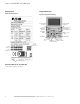
Step 3—Menu Navigation Step 3—Menu Navigation Menu Structure Table 4.
Step 3—Menu Navigation Menu Navigation This section provides basic instruction on navigating each section in the menu structure. Figure 5. Main Menu Navigation PowerXL DG1 Series Adjustable Frequency Drives MN040012EN—March 2014 www.eaton.
Step 4—Startup Wizard Step 4—Startup Wizard Startup Wizard Table 5. Startup Wizard Instructions In the Startup Wizard, you will be prompted for essential information needed by the drive so that it can start controlling your process. In the Wizard, you will need the following keypad buttons: Item Description 1 Startup Wizard Press OK? 2 Language 0 = English 1 = ѝ᮷ 2 = Deutsch 3 Real Time Clock yy.mm.
Step 5—Standard Parameter List Step 5—Standard Parameter List Introduction ● Reference frequency limit supervision The Standard Application is typically used in basic motor control scenarios where multiple pump control, PID loops, or advanced control loops are not required. It provides the ability for the user to define its local and remote control and reference signals. In addition there is the ability to scale the analog input and output signals to be read based off the desired motor response.
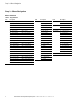
Step 5—Standard Parameter List Control I/O Configuration ● ● Run 240 Vac and 24 Vdc control wiring in separate conduit Communication wire to be shielded Table 6. I/O Connection SW1 AI1 0–10V AI2 SW1 AI2 SW2 AI2 0–20 mA AI2 0–20 mA AI2 0–10V AI2 10–10V SW2 On Off Res Pin i 10 (RS-485 matching resistor) Signal Name Signal Default Setting Description 1 +10V Ref.
Step 5—Standard Parameter List Standard Application—Parameters List On the next pages you will find the lists of parameters within the respective parameter groups. The parameter descriptions are given on Page [?], “Description of Parameters.” The descriptions are arranged according to the parameter number.
Step 5—Standard Parameter List Table 7. Monitor—M, continued Code Parameter Min. Max.
Step 5—Standard Parameter List Table 8. Operate Mode—O Code Parameter O1 Output Frequency O2 O3 O4 Min. Max. Unit Default ID Hz 0.00 1 Freq Reference Hz 0.00 24 Motor Speed rpm 0 2 Motor Current A 0.0 3 O5 Motor Torque % 0.0 4 O6 Motor Power % 0.0 5 O7 Motor Voltage V 0.0 6 O8 DC-link Voltage V 0 7 O9 Unit Temperature °C 0.0 8 O10 Motor Temperature % 0.0 9 R12 2 Keypad Reference Par. P1.1 Par. P1.2 Hz 0.00 141 Note Table 9.
Step 5—Standard Parameter List Table 9. Basic Parameters—P1, continued Code Parameter Default ID Note P1.13 12 Local Reference Min. Max. Unit 6 136 0 = AI1 1 = AI2 2 = Slot A: AI1 3 = Slot B: AI1 4 = AI1 Joystick 5 = AI2 Joystick 6 = Keypad 7 = Fieldbus Ref 9 = Max Frequency 10 = AI1 + AI2 11 = AI1 –AI2 12 = AI2–AI1 13 = AI1 * AI2 14 = AI1 or AI2 15 = MIN(AI1,AI2) 16 = MAX(AI1,AI2) P1.14 12 Remote1 Reference 1 137 See P1.12 P1.
Step 5—Standard Parameter List Table 10. Analog Input—P2, continued Code Parameter Min. Max. Unit Default ID P2.20 2 AI2 Joystick Offset –50.00 50.00 % 0.00 134 Note P2.21 2 AI Ref Scale Min Value 0.00 Par. P2.22 Hz 0.00 144 P2.22 2 AI Ref Scale Max Value Par. P2.21 400.00 Hz 0.00 145 Min. Max. Unit Default ID Note Table 11. Digital Input—P3 Code Parameter P3.
Step 5—Standard Parameter List Table 11. Digital Input—P3, continued Code Parameter Default ID Note P3.15 2 Accel/Decel Time Set Min. Max. Unit 0 195 See P3.2 P3.16 2 Accel/Decel Prohibit 0 201 See P3.2 P3.17 2 No Access To Param 0 215 See P3.2 P3.21 2 Remote Control 9 196 See P3.2 P3.22 2 Local Control 0 197 See P3.2 P3.23 2 Remote1/2 Select 0 209 See P3.2 P3.26 2 DC Brake Enable 0 202 See P3.2 P3.32 2 Jog Enable 0 199 See P3.2 P3.
Step 5—Standard Parameter List Table 13. Digital Output—P5 Code Parameter Default ID Note P5.1 2 DO1 Function Min.
Step 5—Standard Parameter List Table 13. Digital Output—P5, continued Code Parameter P5.15 2 Temp Limit Supv P5.16 2 Temp Limit Supv Val P5.17 2 Power Limit Supv P5.18 2 Power Limit Supv Val P5.19 2 Min. –10.0 Max. ID Note 165 See P5.11 166 0 167 0.0 168 AI Supv Select 0 170 0 = AI1 1 = AI2 P5.20 2 AI Limit Supv 0 171 See P5.11 P5.21 2 AI Limit Supv Val 0.00 100.00 % 0.00 172 P5.30 RO1 On Delay 0 320 s 0 2111 P5.31 RO1 Off Delay 0 320 s 0 2112 P5.
Step 5—Standard Parameter List Table 14. Drive Control—P7, continued Code Parameter P7.22 2 Power Loss Function Min. Max. P7.23 2 Power Loss Time 0.3 5.0 P7.24 Currency 0 8 P7.25 Energy Cost P7.26 Data Type 0 4 P7.27 Energy Savings Reset 0 Min. Unit Default ID Note 0 267 0 = Disabled 1 = Enabled 2.0 268 $ 2121 0 2122 s 0 2123 0 = Cumulative 1 = Daily Avg 2 = Monthly Avg 3 = Yearly Avg 1 s 0 2124 0 = No Action 1 = Reset Max.
Step 5—Standard Parameter List Table 16. Protections—P9 Code Parameter P9.1 12 4 mA Input Fault P9.2 12 4 mA Fault Frequency P9.3 12 P9.4 12 Min. Default ID Note 0 306 0 = No Action 1 = Warning 2 = Warning: Previous Freq 3 = Warning: Preset Freq 4 = Fault 5 = Fault, Coast 0.00 331 External Fault 2 307 See P9.11 Input Phase Fault 2 332 See P9.11 P9.5 12 Uvolt Fault Response 2 330 See P9.11 P9.6 12 Output Phase Fault 2 308 See P9.11 P9.7 12 Ground Fault 2 309 See P9.
Step 5—Standard Parameter List Table 16. Protections—P9, continued Code Parameter Min. Max. P9.32 2 External Fault Attempts 0 10 P9.33 2 Underload Attempts 0 10 1 336 P9.34 12 RTC Fault 1 955 See P9.11 P9.35 12 PT100 Fault Response 2 337 See P9.11 P9.36 12 Replace Battery Fault Response 1 1256 See P9.11 P9.37 12 Replace Fan Fault Response 1 1257 See P9.11 P9.38 12 IP Address Confliction Resp P9.39 Cold Weather Mode P9.40 Cold Weather Voltage Level 0 20 P9.
Step 5—Standard Parameter List Table 19. FB Data Output Sel—P20.1 Code Parameter Default ID P20.1.1 2 FB Data Output 1 Sel Min. Max. Unit 1 1556 P20.1.2 2 FB Data Output 2 Sel 2 1557 P20.1.3 2 FB Data Output 3 Sel 3 1558 P20.1.4 2 FB Data Output 4 Sel 4 1559 P20.1.5 2 FB Data Output 5 Sel 5 1560 P20.1.6 2 FB Data Output 6 Sel 6 1561 P20.1.7 2 FB Data Output 7 Sel 7 1562 P20.1.8 2 FB Data Output 8 Sel 359 1563 Note Table 20. Modbus RTU/BACnet MS/TP—P20.
Step 5—Standard Parameter List Table 21. EtherNet/IP / Modbus TCP—P20.3 Code Parameter P20.3.1 IP Address Mode Min. Max. Unit Default ID Note 1 1500 0 = Static IP 1 = DHCP with AutoIP P20.3.2 Active IP Address 1507 P20.3.3 Active Subnet Mask 1509 P20.3.4 Active Default Gateway 1511 P20.3.5 MAC Address P20.3.6 Static IP Address 192.168.1.254 1513 P20.3.7 Static Subnet Mask 255.255.255.0 1503 P20.3.8 Static Default Gateway 192.168.1.1 1505 P20.3.
Step 5—Standard Parameter List Table 22. Basic Setting—P21.1, continued Code Parameter P21.1.6 Parameter Comparison P21.1.7 Password P21.1.8 Min. Default ID Note 0 623 0 = No 1 = Compare with Keypad 2 = Compare with Default 3 = Compare with Set 1 4 = Compare with Set 2 0 624 Parameter Lock 0 625 0 = Change Enable 1 = Change Disable P21.1.9 Multimonitor Set 0 627 See P21.1.8 P21.1.10 Default Page 0 628 0 = None 1 = Main Menu 2 = Multi-Monitor P21.1.
Step 5—Standard Parameter List Table 25. User Info—P21.4 Code Parameter Default ID P21.4.1 Real Time Clock Min. Max. Unit 0.0.0.1:1:13 566 P21.4.2 Daylight Saving 0 582 P21.4.3 Total MWh Count Mwh Total Power Day Count 603 P21.4.5 Total Power Hr Count 606 P21.4.6 Trip MWh Count Clear Trip MWh Count P21.4.8 Trip Power Day Count P21.4.9 Trip Power Hr Count P21.4.10 Clear Trip Power Count 0 = Off 1 = EU 2 = US 601 P21.4.4 P21.4.
Step 6—Faults and Warning Codes Step 6—Faults and Warning Codes Under this menu, you can find Active faults, History faults and Fault codes. Table 26. Active Faults Menu Function Note Active Faults When a fault/faults appear(s), the display with the name and fault time of the fault will be pop. Press DETAIL to see the fault data. The Active Faults submenu shows the list of faults. Select the fault and push DETAIL to see the fault data.
Step 6—Faults and Warning Codes Fault Code Fault Name Fault Type Default Fault Type Possible Cause Remedy 8 UnderVoltage Configurable 1 Fault DC link voltage is under the voltage limits defined: • Most probable cause: Too low a supply voltage • AC drive internal fault • Defect input fuse • External charge switch not closed Note: This fault is activated only if the drive is in Run state. In case of temporary supply voltage break reset the fault and restart the AC drive Check the supply voltage.
Step 6—Faults and Warning Codes Fault Code Fault Name Fault Type Possible Cause Remedy 28 Device Removed Fault Optional board removed from slot, or power board removed from control board Device no longer available 29 Device Unknown Fault Unknown device connected (power board/option board Device no longer available 30 IGBT OverTemp Fault IGBT temperature is too high • Check loading • Check motor size • Decrease switching frequency 31 Encoder Fault Fault • • • • • • • • • 32 AIN<4 m
Eaton is dedicated to ensuring that reliable, efficient and safe power is available when it’s needed most. With unparalleled knowledge of electrical power management across industries, experts at Eaton deliver customized, integrated solutions to solve our customers’ most critical challenges. Our focus is on delivering the right solution for the application. But, decision makers demand more than just innovative products.