
Technical Bulletin

Modbus RTU On-Board Communications
10 PowerXL DG1 Series VFD MN040010EN—May 2014 www.eaton.com
The function code field of a message frame contains two
characters (ASCII) or eight bits (RTU). Valid codes are in the
range of 1–255 decimal. When a message is sent from a
master to a slave device, the function code field tells the
slave what kind of action to perform.
Examples are to read the ON/OFF states of a group of
discrete coils or inputs; to read the data contents of a group
of registers; to read the diagnostic status of the slave; to
write to designated coils or registers; or to allow loading,
recording or verifying the program within the slave.
When the slave responds to the master, it uses the function
code field to indicate either a normal (error-free) response or
that some kind of error occurred (called an exception
response). For a normal response, the slave simply echoes
the original function code. For an exception response, the
slave returns a code that is equivalent to the original function
code with its most significant bit set to a logic state of 1.
The data field is constructed using sets of two hexadecimal
digits, in the range of 00 to FF hexadecimal. These can be
made from a pair of ASCII characters, or from one RTU
character, according to the network’s serial transmission
mode.
The data field of messages sent from a master to slave
devices contains additional information that the slave must
use to take the action defined by the function code. This can
include items like discrete and register addresses, the
quantity of items to be handled, and the count of actual data
bytes in the field.
If no error occurs, the data field of a response from a slave to
a master contains the data requested. If an error occurs, the
field contains an exception code that the master application
can use to determine the next action to be taken.
Two kinds of checksum are used for standard Modbus
networks. The error checking field contents depend upon the
transmission method that is being used.
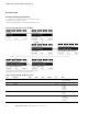
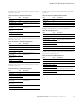
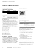
Supported Functions
Table 8. Functions
Note: Broadcasting can be used with codes 0x05, 0x06,
0x0F and 0x10.
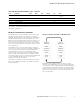
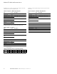
Example of the request to read coils 2000–2003 from Slave
device 18.
Table 9. Request to Read Coils
Function Code Description
0x01 Read Coils
0x02 Read Discrete Inputs
0x03 Read Holding Registers
0x04 Read Input Registers
0x05 Write Single Coil
0x06 Write Single Register
0x07 Read Exception Status
0x08 Read Diagnostics
(Only support 0x00 Return Query Data)
0x0F Write Multiple Coils
0x10 Write Multiple Registers
0x17 Read/Write Multiple Registers
0x2B/0x0E Read device identity
Item Code Description
Slave address 0x12
Function code 0x01
Start address High 0x07 Starting address 0x07D0 hex (= 2000)
Start address Low 0xD0
Number of coils High 0x00 Number of coils 0x0003 hex (= 3)
Number of coils Low 0x03
CRC High 0x7E
CRC Low 0x25